
Mandy's Moods
An LED-illuminated desktop sign

Note: All photographs appearing on this page are freely usable for any purpose. Links to high-resolution versions of the pictures appear below each picture.
Wiring the Mandy's Moods Electronics
Electronics Components You Will Need
The electronics component of the Mandy's Moods project is relatively simple. You'll need the following parts:
(3) Adafruit Neopixel sticks (RGB, 8 LEDs per stick)
(1) Adafruit 5V Trinket microcontroller (an Arduino IDE compatible product)
(1) Adafruit 5V 2A "wall wart" power supply (not shown below)
(1) 1000 µF capacitor (6.3V or higher)
(1) Female 2.1 mm power jack with screw terminals
Plus some solder and a few feet of hookup wire (there are six spools of hookup wire in the black box in the picture below; you don't need that much but having hookup wire laying around is not a bad idea if you do electronics projects)
You'll need a soldering iron to assemble the components. I used a hot glue gun to glue everything in place, though other adhesives will likely work fine too.
The "Bill of Materials" link on the right-hand side lists all the parts you will need as well as links to web pages for most of the items.
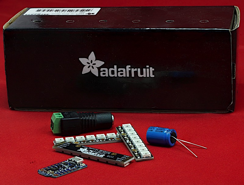 High-resolution image shot with a Canon EOS 5D MII
Soldering the Neopixel Sticks Together
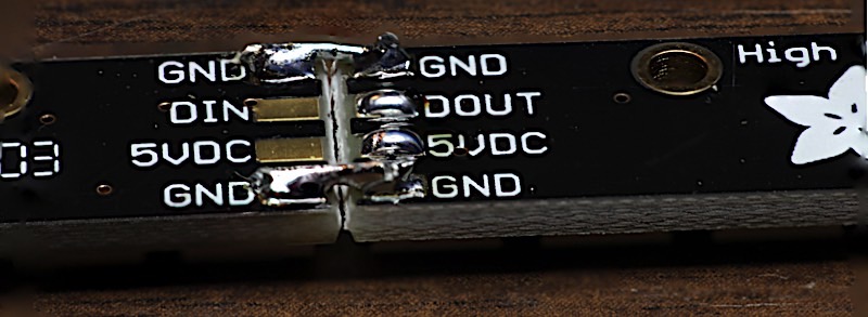
The first place to begin is with the three Neopixel strips. These strips need to be soldered together into a single long strip (24 LEDs). If you look closely at these sticks, you notice four gold "fingers" on each side of the board. The left-hand fingers are labeled GND, DOUT, 5VDC, and GND (from top to bottom). The right-hand fingers are labeled GND, DIN, 5VDC, and GND (also from top to bottom). We want to solder the two boards together by soldering the following fingers together:
- Left board top GND to right board top GND
- Left board DIN to right board DOUT
- Left board 5VDC to right board 5VDC
- Left board bottom GND to right board bottom GND
To begin with, "tin" the fingers on one of the boards (in the picture below, this is the right board) by putting a small drop of solder on each finger:
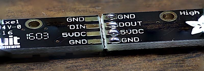
High-resolution image shot with a Canon EOS 5D MII
Next, strip off a small section of hookup wire, bend it at a 90-degree angle (from the rest of the wire), and tin the wire with a small amount of solder. Note that the amount of insulation you strip off should expose sufficient wire to cover both top GND pads.

High-resolution image shot with a Canon EOS 5D MII
Now solder the wire onto the top right GND pad by setting the wire on the blob of solder and touching the soldering iron to the combination (the joint below looks pretty ugly because it is magnified quite a bit, in reality it doesn't look so bad in life-sized scale).
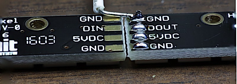
High-resolution image shot with a Canon EOS 5D MII
Next, solder the wire to the left top GND pad.
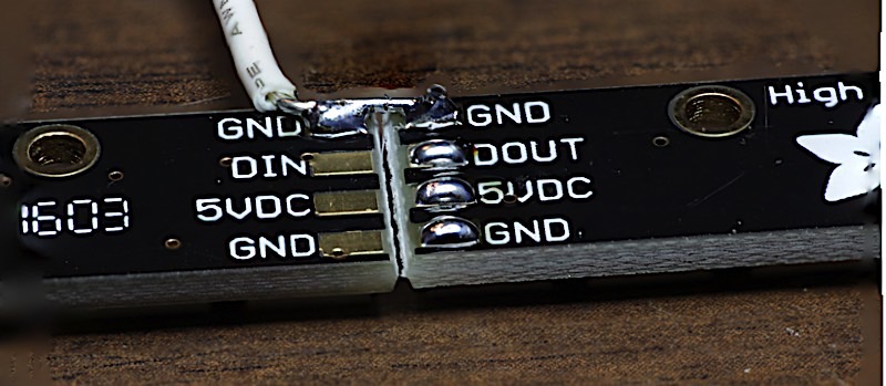
High-resolution image shot with a Canon EOS 5D MII
Next, cut the wire off. Then repeat for the other three pads. Start with the GND pads on the bottom. This helps you to keep the two boards aligned straight. Ultimately, all three Neopixel Sticks must form a straight line if they are to properly fit in the Mandy's Moods box.
High-resolution image shot with a Canon EOS 5D MII
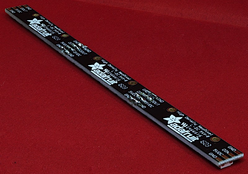
Here's what the three assembled Neopixels sticks should look like:
High-resolution image shot with a Canon EOS 5D MII
The next step is to solder wires on the Neopixel strip. If you have three colors of hookup wire, that's best because we can use a different color for each signal; if you have a single color, that's fine -- this is a simple wiring job and it's not that difficult to trace the wires. I happen to have several colors available, I used Red, Black, and Yellow on my strip. The following discussion assumes these three colors, if you don't have three, just use the same color for everything.
First, cut a 6" length of red and black hookup wire. Then cut a 9" length of black hookup wire. Finally, cut 5" lengths of red, black, and yellow hookup wires.
Solder the 6" wires onto the top GND and 5VDC fingers on the left side of the strip. Solder the 9" black wire on the bottom GND finger of the right side of the strip. Solder the red 5" wire to the 5VDC finger on the right side. Solder the black 5" wire to the top GND finger on the right side. Finally, solder the yellow 5" wire to the DIN finger on the right side. When you are done, the Neopixel strip should look something like this:
![]()
High-resolution image shot with a Canon EOS 5D MII
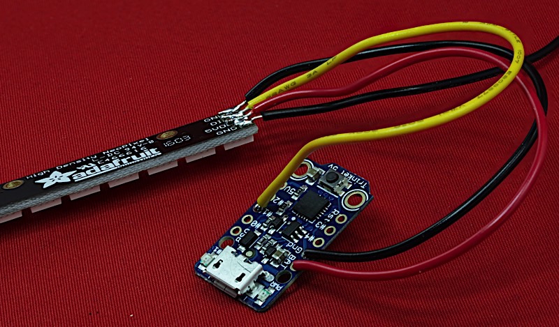
The next step is to wire up the Adafruit 5V Trinket microcontroller. Connect the 5" black wire (top GND) to the GND connector on the Trinket. Connect the 5" red wire (5VDC) to the BAT connector on the Trinket. Finally, connect the 5" yellow wire (DIN) to pin #1 on the Trinket. When you finish, the result should look something like this:
High-resolution image shot with a Canon EOS 5D MII
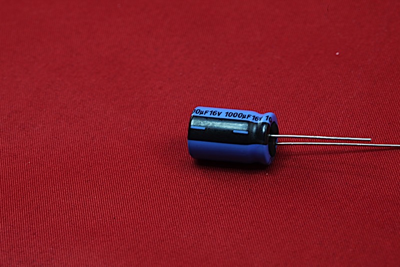
The next step is to wire up the power connector. But before doing that, take a look at the 1000 µF capacitor. On the side of the can (closest to one of the leads) is an indication of the polarity of the capacitor (assuming you have an electrolytic capacitor, which is the most common type for capacitors of this size). The black strip with the "-" sign indicates which led is negative (GND). Typically, this lead is the shorter of the two, as well.
High-resolution image shot with a Canon EOS 5D MII
Now take a look at the 2.1mm barrel jack. You'll notice that the screw terminals are labeled "+" and "-".
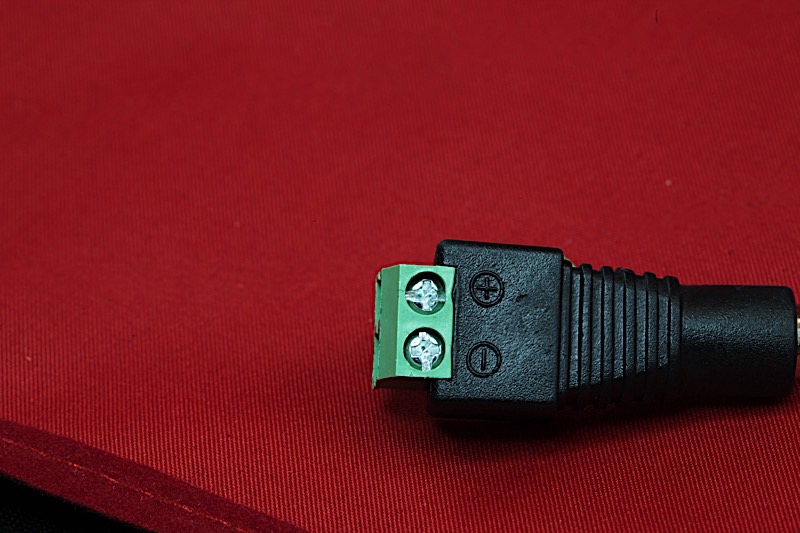
High-resolution image shot with a Canon EOS 5D MII
Trim the leads on the capactor so they are the same length. Unscrew the terminals on the barrel jack (about half way, not all the way out). Insert the leads of the capacitor into the terminals on the barrel jack with the "-" lead in the "-" terminal and the other lead in the "+" terminal. Before tightening any screws, insert the two remaining black wires (from top GND on the left side of the strip and bottom GND on the right side of the strip) into the "-" terminal on the barrel jack. Tighten the "-" screw.
Now insert the red wire (5VDC on the left side of the strip) into the "+" terminal along with the other capacitor lead. Tighten the screw. Your electronics should now look like the following:
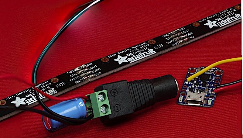
High-resolution image shot with a Canon EOS 5D MII
Now for the smoke test. First, double check all your wiring and make sure there are no shorts between the pads (fingers) on the Neopixel boards. Verify that the capacitor's polarity is correct (the '-' lead is connected to the '-' terminal on the barrel jack) and the positive and negative wires are connected to appropriate places.
Connect a micro USB cable to the Trinket and plug it in to a USB port. If all is well, the green LED on the Trinket should come on (the orange LED may blink on and off for a bit as well). The Neopixel strips won't do anything because the bare Trinket doesn't contain any code to control them, so don't worry if they don't seem to be functioning.
The next hardware step would be to glue the electronics into the Mandy's Moods box. However, it's probably easiest to first install the software before the last hardware step. To learn about that, head on to the next page in this series.
Index:
