
Note: All photographs appearing on this page are freely usable for any purpose. Links to high-resolution versions of the pictures appear below each picture.
Digital Data Acquisition & Control System
PPAC4
4-Channel analog conditioning
High-resolution image shot with a Canon EOS 5D MII
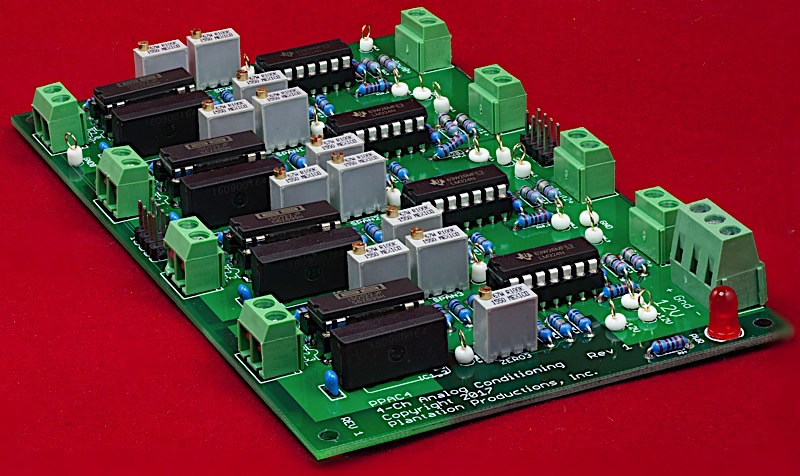
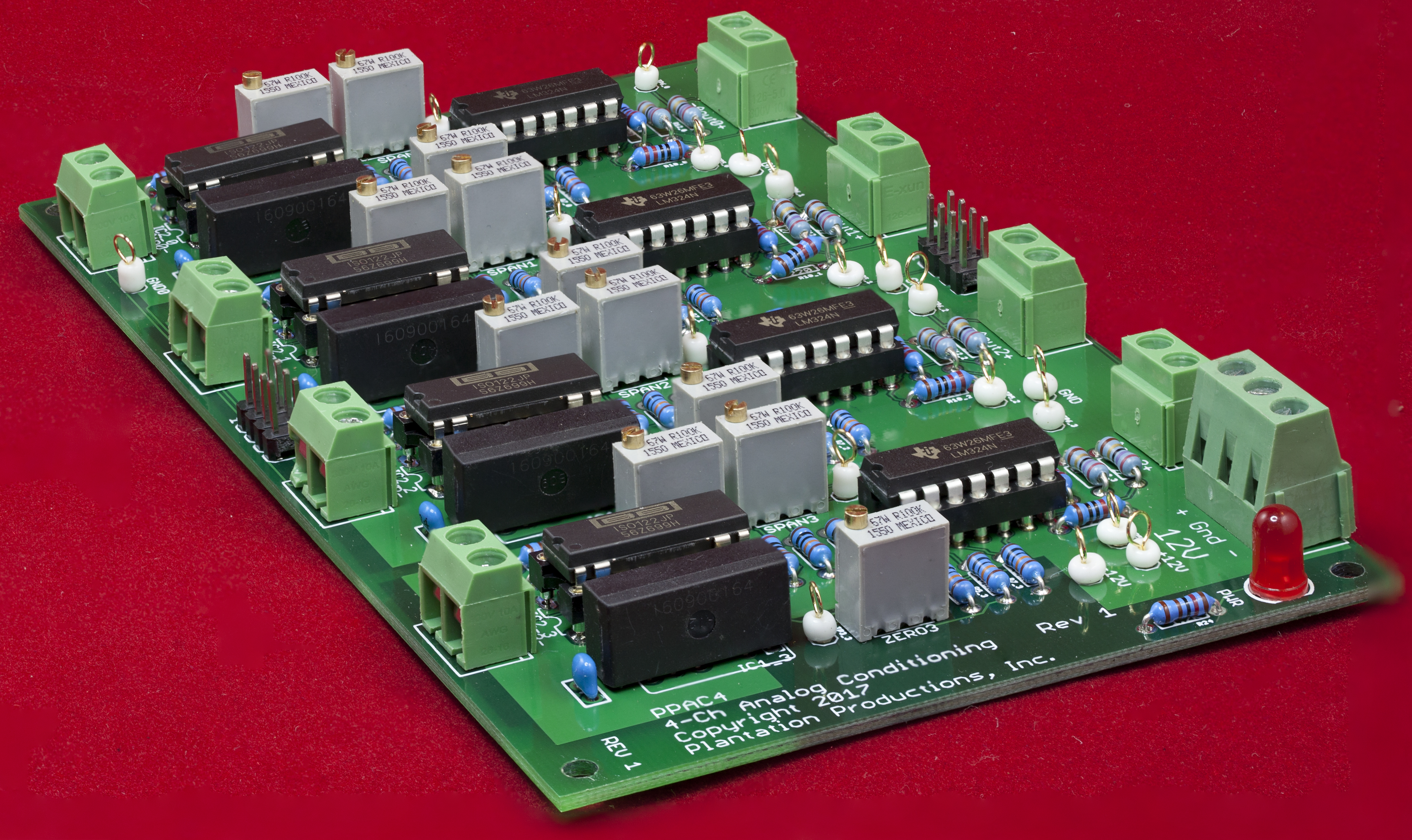
The PPAC4 board is a 4-channel analog conditioning and isolation board for analog input signals. Each channel accepts an input voltage in the range ±10V. This is run through an isolation amplifier and then converted to a pair of differential output signals (0 to 4.096V) that are compatible with the PPAIO-16/4 differential inputs. A +10V input produces a 4.095V output on the (+) terminal and a 0V output on the (-) terminal. A -10V input produces a 0V output on the (+) terminal and a 4.095V output on the (-) terminal. A 0V input produces a 2.048V output on both terminals.
The PPAC4 has the following features:
- Open Source/Open Hardware design (Creative Commons 4.0 license)
- ±12V power supply
- LED indicates when power is applied
- 4 single-ended analog inputs supporting ±10V inputs
- 4 differential (doubled-ended) outputs (producing 0 to 4.095V differential outputs; technically, the differential outputs are 10V, but the PPAIO-16/4 ADC board that the PPAC4 mates to accepts 0 to 4.095V differential inputs).
- Electrical isolation (isolation amplifiers) on each input channel isolating all inputs from each other and from the DAQ system
- Span, zero, and vref pots for all four analog channels
- Compatible with PPAIO-16/4 analog I/O board using direct wiring or an easy connection using an 8-conductor ribbon cable
- Compatible with PPAC420 4-20mA conversion board using direct wiring or an easy connection using an 8-conductor ribbon cable
- Minimum 1kHz bandwidth (note: DAQ system standard firmware scans analog inputs at a 40 Hz rate, so this is 25 times faster than needed by the DAQ firmware)
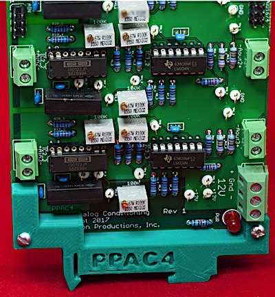
- Optional DIN rail brackets allow installation on 35mm DIN rails
- DIN rail brackets are available in .STL format for 3D-printing
- Full documentation including System Requirements Specifications (SyRS), Hardware Requirements Specifications (HRS), Hardware Inspection list (HI), Hardware Test Cases (HTC), Hardware Test Procedures (HTP), Hardware Design Description (HDD), and (reverse) Traceability Matrix (RTM) are available for the DAQ system, including this board.
Bill of Materials (BOM) for the PPAC4 board:
- (1) 5mm LED
- (1) 1.2 kΩ 1/4-watt 1% resistor
- (8) 2-pin screw terminal (5mm/0.2" centers)
- (1) 3-pin screw terminal (5mm/0.2" centers)
- (12) 100 kΩ PCB trim pots (BI 67W R100K)
- (4) PDM1-S12 isolated power supplies
- (4) ISO122 isolation amplifiers
- (4) LM324 Quad opamps
- (2) 8-pin (2x4) male headers
- (2) 27 Ω 1% resistors
- (8) 220 Ω 1% resistors
- (4) 390 Ω 1% resistors
- (8) 2.2 kΩ 1% resistors
- (16) 100 kΩ 1% resistors
- (4) 200 kΩ 1% resistors
- (12) 0.1µF decoupling capacitors
- (1) PPAC4 PCB
- Optional: (34) test pins
- Optional: one set of horizontal 35mm DIN rail mounts for DAQ boards
Note: If you only want a few PPAC4 PCBs, contact Plantation Productions (randy@plantation-productions.com) to see if there are any in stock. Bare boards are $25 each plus shipping; fully assembled and tested boards are $499 each. If you need more than a couple PCBs and you're not in a huge hurry, it costs about $150 (plus about 4-6 weeks) to have a set of 10 manufactured and shipped to you from China. I use Seeed Studio Fusion PCD service (https://www.seeedstudio.com/fusion.html). The PPDIO96 PCBs are four-layer boards. Here are the Gerber files for them (provide these files to Seeed Studio or your personal PCB manufacturer).
If you want to modify or enhance the PPAC4 design, or re-layout the PCB using Eagle, here are the Eagle files:
PPAC4 Eagle files (Schematic and board layout)
If you simply want to view the schematic on-line, you'll find that here:
The DIN rails were created using AutoDesk's Fusion 360 (to produce STL files) and I personally print the results on a Lulzbot Taz6 3D printer using ABS filament (ABS is recommended for this job, PLA and PETG are a bit brittle). The STL files can be found here:
PP Standard DIN Rail Brackets 3D printer files
PPAC4 Vertical DIN Rail Bracket 3D printer files
High-resolution image shot with a Canon EOS 5D MII
PPAC4 Board Layout
Connecting a PPAC4 board to a DAQ System (via PPAIO-16/4)
As a general rule, the PPAC4 board connects some external analog signal (±10V) to a differential input pair on a PPAIO-16/4 board. The external analog inputs (singled-ended) connect to the AIN0, AIN1, AIN2, and AIN3 terminal pairs on the PPAC4 board. The AOUT0, AOUT1, AOUT2, and AOUT3 terminal pairs connect to differential input pairs on the PPAIO-16/4.
It is also possible to use an 8-pin ribbon cable (2x4 IDC connectors) to connect a PPAC4 board to a PPAIO-16/4 board:
As the PPAIO-16/4 board can handle up to 8 differential inputs, it is possible to connect two PPAC4 boards to a single PPAIO-16/4 board. Note that there are two 8-pin (2x4) headers to connect to the PPAC4 on the PPAIO-16/4: one for AIN0-AIN7 (differential inputs AIN0d-AIN3d) and one header for AIN0-AIN15 (differential inputs AIN4d-AIN7d).
Connecting a PPAC420 (4-20mA conversion) board to a PPAC4 Board
You can also use a PPAC4 board to process the output from a PPAC420 (4-20mA conversion) board. For more details, see the page describing the PPAC420.
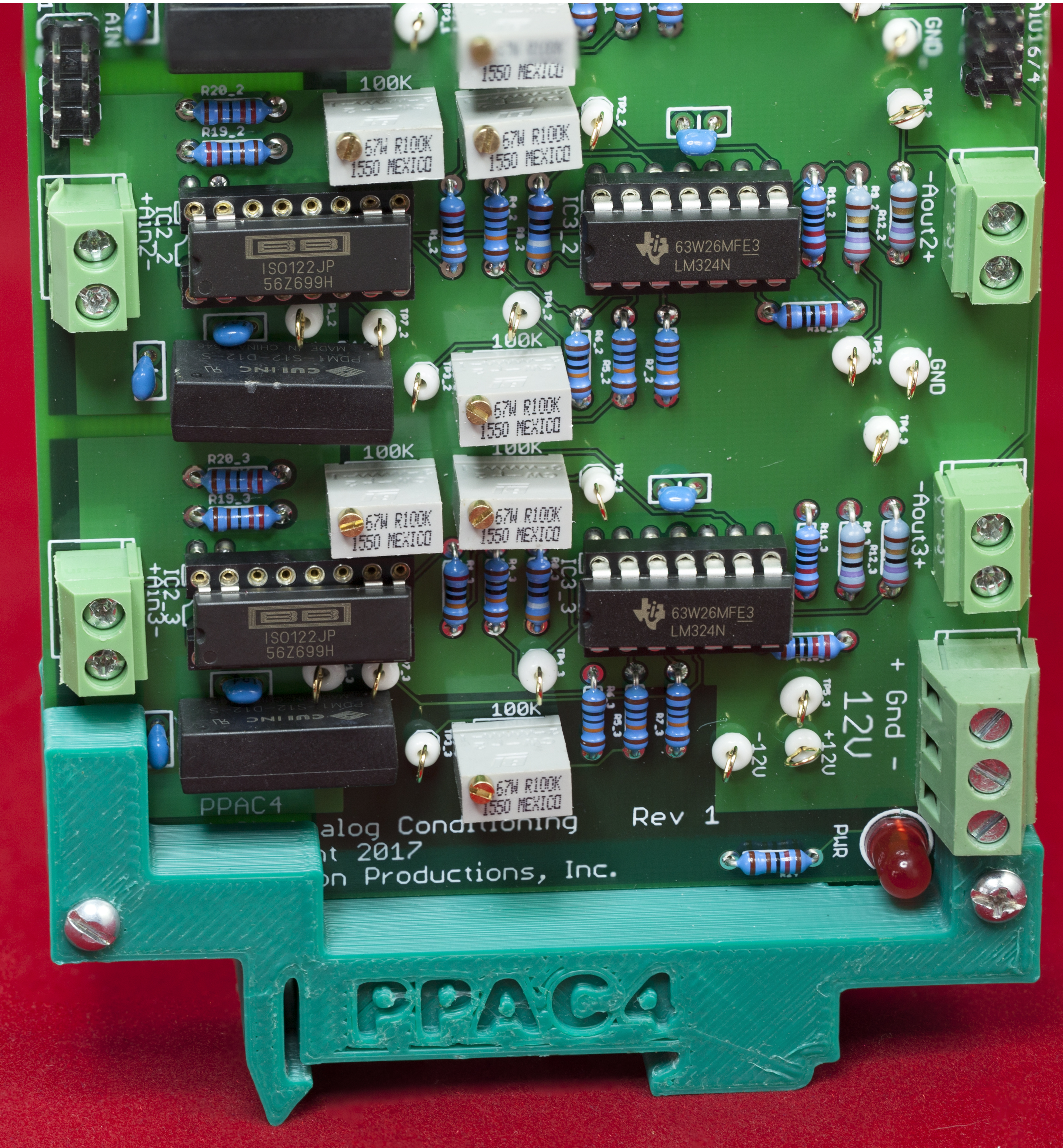
Calibrating the PPAC4 Board
The PPAC4 board contains three calibration pots for each channel to set the ZERO, SPAN, and VREF values. The ZERO pot sets the voltage offset (zero point) for each channel.
The ZERO pot is useful because the ISO122 isolation amplifier always adds a small voltage offset to the output of the amplifier (that is, if you put in exactly 0V as input to the ISO122 you'll probably not get exactly 0V as the output from the amp -- the ISO122 can add a small negative or positive voltage offset to the input voltage). Also, it's unlike the plus and minus legs of the ±12V power supply are exactly equal in magnitude, so the ZERO pot can help offset for differences there as well as inexact resistor values in the opamp circuits.
The SPAN pot adjusts the overall gain of the opamp circuit (note that a dual opamp circuit follows the isolation amplifier; the isolation amplifier has a gain of 1 which is not adjustable). The PPAC4 board accepts a ±10V input and produces a differential output (differential) output. A -10V input should produce a "maximum" voltage on the (-) terminal and 0V (or thereabouts) on the (+) terminal. A +10V should produce a "maximum" voltage on the (+) terminal and 0V on the (-) terminal. The "maximum" voltage depends upon what you intend to connect the PPAC4 board to. If you are connecting it to a PPAIO-16/4 board and you're using the programming gain setting of '1', the "maximum" voltage will be 4.095V. You use the SPAN pot to set this maximum voltage range.
The VREF pot picks the voltage at which the (+) and (-) terminals will have an equal voltage output (that is, corresponding to the 0V point). Normally, as the first stage of the opamp circuit produces a 0 to 5V span, you adjust the VREF pot to produce 2.5V. This means that 2.5V will register as a zero on the PPAIO-16/4 ADC (as both the plus and minus terminals will be the same value, 2.5V, and their difference is zero).
Calibrating the PPAC4 consists of iterating the following steps for ±10V operation (assumption: you're connecting the PPAC4 to a PPAIO-16/4 with the operating range of 0 to 4.095V on the differential inputs):
- First, begin by setting the zero voltage (measured at test pin TP3_n) to around -2.0 to -2.1V by adjusting the ZERO pot.
- Also, set TP7_n to around 2.048V by adjusting the VREF pot.
- Next, supply an input voltage of -10V to the channel and measure the amplifier section output voltage on test pin TP4_n (where n is the channel number, 0 to 4).
- Adjust the ZERO pot until you read a voltage of 0V on TP4_n.
(If you don't have a power supply that produces postive and negative voltages, just swap the plus and minus leads on the power supply to get negative voltages.)
- Supply an input voltage of +10V to the channel you're calibrating and measure the amplifier section output voltage on test pin TP4_n.
- Adjust the SPAN pot until you read a voltage of +4.096V on TP4_n. Note: if the initial reading is greater than +4.096V, reduce it to a value less than +4.096V and then slowly adjust the output back up to +4.096V.
- Repeat steps 3 through 6 until the ZERO point and SPAN are reasonably close (note that adjusting one pot will affect the other pot's results, so you will have to iterate over this process several times.
Note that because of inaccuracies in the components, the power supplies, temperature, humidity, etc., it is unlikely that you will exactly 0V, and 4.095V.
Once you've set the ZERO and SPAN pots appropriately, the next step in the calibration is to set the VREF pot. The VREF pot selects the voltage that will be the dividing point between the plus and minus terminals in the differential output. Use the following steps to set the VREF pot:
- Supply -10V to the channel input.
- Adjust the VREF pot so that the (-) pin (TB6_n) is close to 4.095V and the (+) pin (TP5_n) is close to 0V (their difference should be approximately 4.095V).
- Supply +10V to the channel input.
- Adjust the VREF pot so that the (-) pin (TB6_n) is close to 0V and the (+) pin (TP5_n) is close to 4.095V (their difference should be approximately 4.095V).
- If there is considerable difference between the -10V and +10V readings, you can adjust the SPAN and ZERO pots to try and close in the difference.
- Supply an input voltage of 0V to the channel input.
- Measure the voltages on the TP5_n and TP6_n test pins.
Ultimately, the 0V setting for VREF is the most important. Steps 7 and 8 are critical and should be repeated as the last step in the calibration operation
This calibration process assumes a ±10V input and a 0 to 4.095V differential output. The 0 to 4.095V output assumes that you're feeding the differential output to a PPAIO-16/4 input when the ADS1115 programmable gain set to 1 (0 to 4.095V). Note that if you have a ±5V input, you can do this same calibration (include ±10V inputs) and simply set the gain to 2 (0 to 2.047V). This will boost the output from the PPAC4 by a factor of two, effectively turning the ±5V into ±10V. Likewise, you can handle ±2.5V or ±1.25V inputs by setting the gain to 3 (0 to 1.023V) or 4 (0 to 0.512V).
Note that you can only get a full 16-bit range on the ADS1115 (the ADC chip on the PPAIO-16/4) when operating with positive and negative input values. If your voltage input is non-negative (e.g., 0 to 10V) then only 15 bits of precision are available. If you have some input voltage that is not ±10V, ±5V, ±2.5V, or ±1.25V you can alway use the SPAN pot on an AC4 channel to boost/reduce it to the next larger/lower range. For example, if you have a 0 to 1V input, you can use the SPAN pot to boost it to 0 to 1.25V to get a full 15 bits of precision out of the ADS1115 ADC IC.
Programming the PPAC4 Board
The PPAC4 board is pure hardware. There is no PPAC4-specific software programming possible. The PPAC4 connects to the PPAIO-16/4 board and the software controls the ADCs (and DACs) on that board. Therefore, programming the PPAC4 consists of programming PPAIO-16/4 board. See the web page on the PPAIO-16/4 board for more details.