
Note: All photographs appearing on this page are freely usable for any purpose. Links to high-resolution versions of the pictures appear below each picture.
EtherPort Data Acquisition & Control System
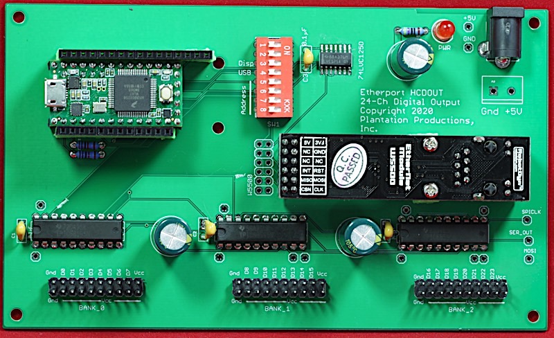
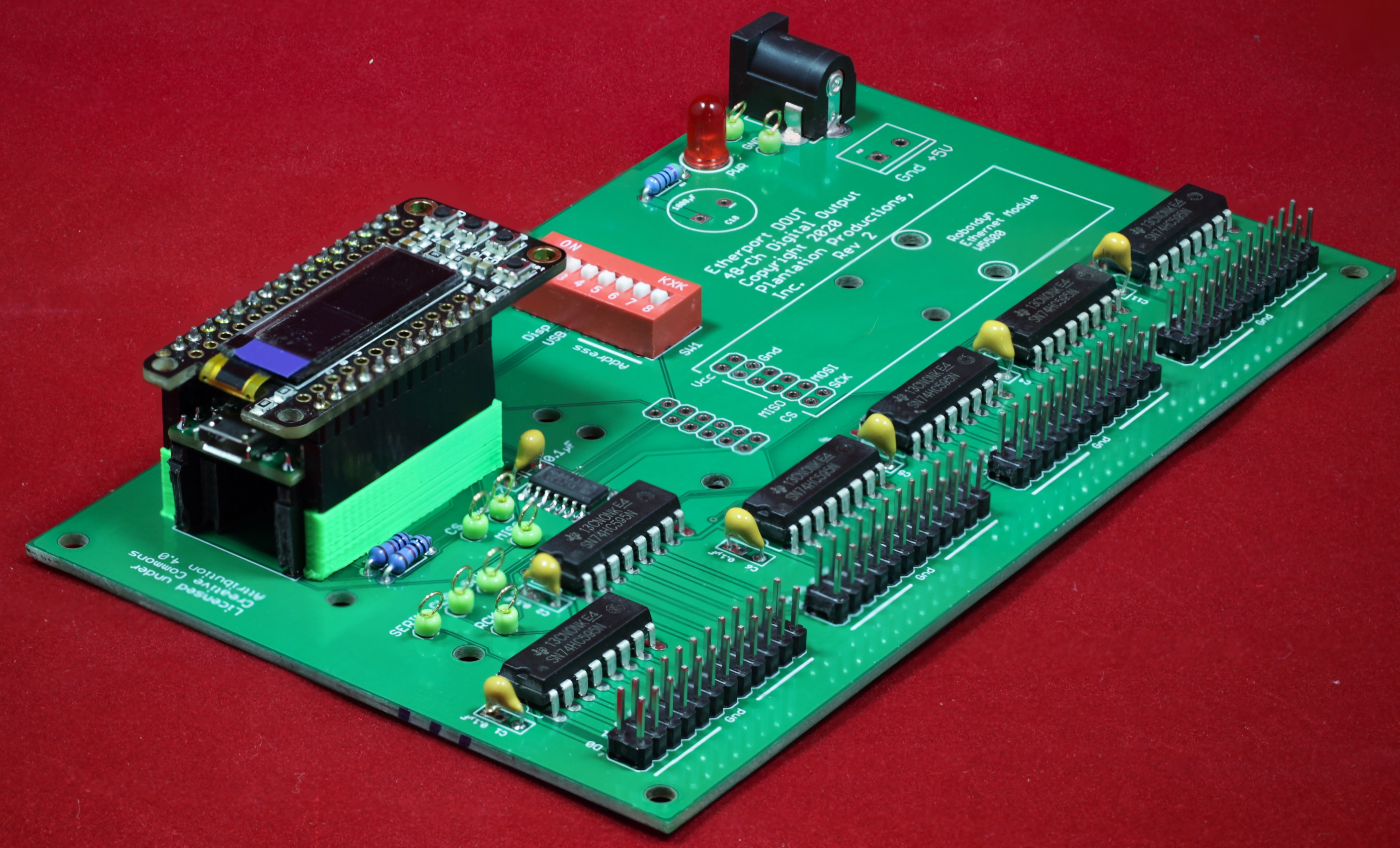
EtherPort HCDOUT
24-Channel high-current digital output board
High-resolution image
The EtherPort HCDOUT board is a 24-channel digital input board. The EtherPort HCDOUT offers the following features:
- Open Source/Open Hardware design (Creative Commons 4.0 license)
- Single 5V power supply
- LED indicates when power is applied
- 24 independent output bits (open drain outputs capable of sinking 150 mA)
- 24 output pins divided up into 3 banks of 8 bits each
- Optional DIN rail brackets allow installation on 35mm DIN rails
- DIN rail brackets are available in .STL format for 3D-printing
- Full documentation including System Requirements Specifications (SyRS), Hardware Requirements Specifications (HRS), Hardware Inspection list (HI), Hardware Test Cases (HTC), Hardware Test Procedures (HTP), Hardware Design Description (HDD), and (reverse) Traceability Matrix (RTM) are available for the EtherPort system, including this board.
Bill Of Materials
Bill of Materials (BOM) for the EtherPort HCDOUT board:
- (1) 5mm LED
- (1) 470 Ω 1/4-watt 1% resistor
- (2) 4.7 kΩ 1/4-watt 1% resistor
- (4) 0.1 µF decoupling capacitors
- (3) 1000 µF electrolytic capacitor
- (1) 2-pin screw terminal (5mm/0.2" centers) or (1) 5.5mm Barrel Jack for power
- (3) 20-pin (2x10) male headers (ribbon cable connectors)
- (1) 74HC125 4-ch tri-state buffer (SOIC-14)
- (3) tpic6b595 serial-in parallel-out shift registers (DIP)
- (1) 8-position DIP switch
- (1) 1x12 female header with long pins (Feather bus)
- (1) 1x16 female header with long pins (Feather bus)
- (1) Teensy 3.2 with (full) headers
- (1) EtherPort HCDOUT PCB
- (1) Adafruit Ethernet Featherwing -or- Robotdyn W5500 Ethernet module (if Ethernet connection is desired)
- (1) 2x6 female header with long pins (if using Robotdyn W5500 Ethernet module)
- Optional: (7) test pins
- Optional: (3) 20-pin machined sockets
- Optional: (1) set of female headers for use as a Teensy socket
- Optional: one set of horizontal 35mm DIN rail mounts for EtherPort/DAQ boards
- Optional: one EtherPort HCDOUT vertical 35mm DIN rail mount
- Optional: 1 set of 3D-printed Featherwing shrouds for the Featherwing headers (STL files here and here)
PCB Availability and Files
Note: If you only want a few EtherPort HCDOUT PCBs, contact Plantation Productions (randy@plantation-productions.com) to see if there are any in stock. Bare boards are $25 each plus shipping; fully assembled and tested boards are $499 each. If you need more than a couple PCBs and you're not in a huge hurry, it costs about $50 (plus about 4-6 weeks) plus shipping to have a set of 10 manufactured and shipped to you from China. I use Seeed Studio Fusion PCD service (https://www.seeedstudio.com/fusion.html). The EtherPort HCDOUT PCBs are two-layer boards.
| Description | Link |
|---|---|
| Gerber files for PCB (provide these files to Seeed Studio or your personal PCB manufacturer) | EtherPort HCDOUT Gerber Files for PCB |
| Eagle schematic capture and PCB layout files. Use these if you want to modify or enhance the EtherPort HCDOUT design, or re-layout the PCB using Eagle | EtherPort HCDOUT Eagle files (Schematic and board layout) |
| On-line schematic (PDF format) | |
| PP Standard DIN rails (STL format for 3D printer) | PP Standard DIN Rail Brackets 3D printer files |
| Adjustable DIN rail bracket (STL format for 3D printer) | Adjustable DIN Rail Bracket 3D printer file |
Vertical DIN rail bracket (STL format for 3D printer) |
EtherPort DOUT Vertical DIN Rail Bracket |
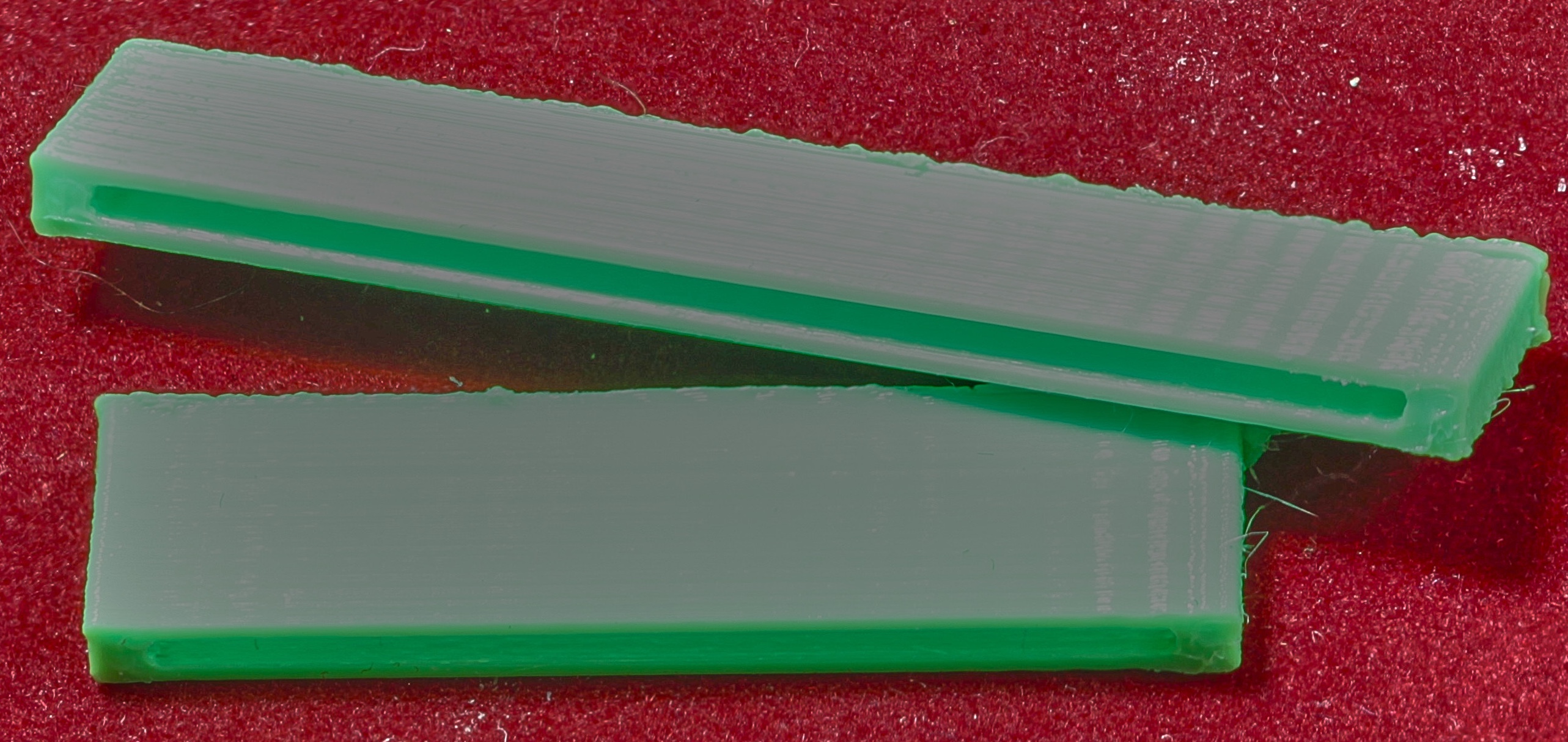
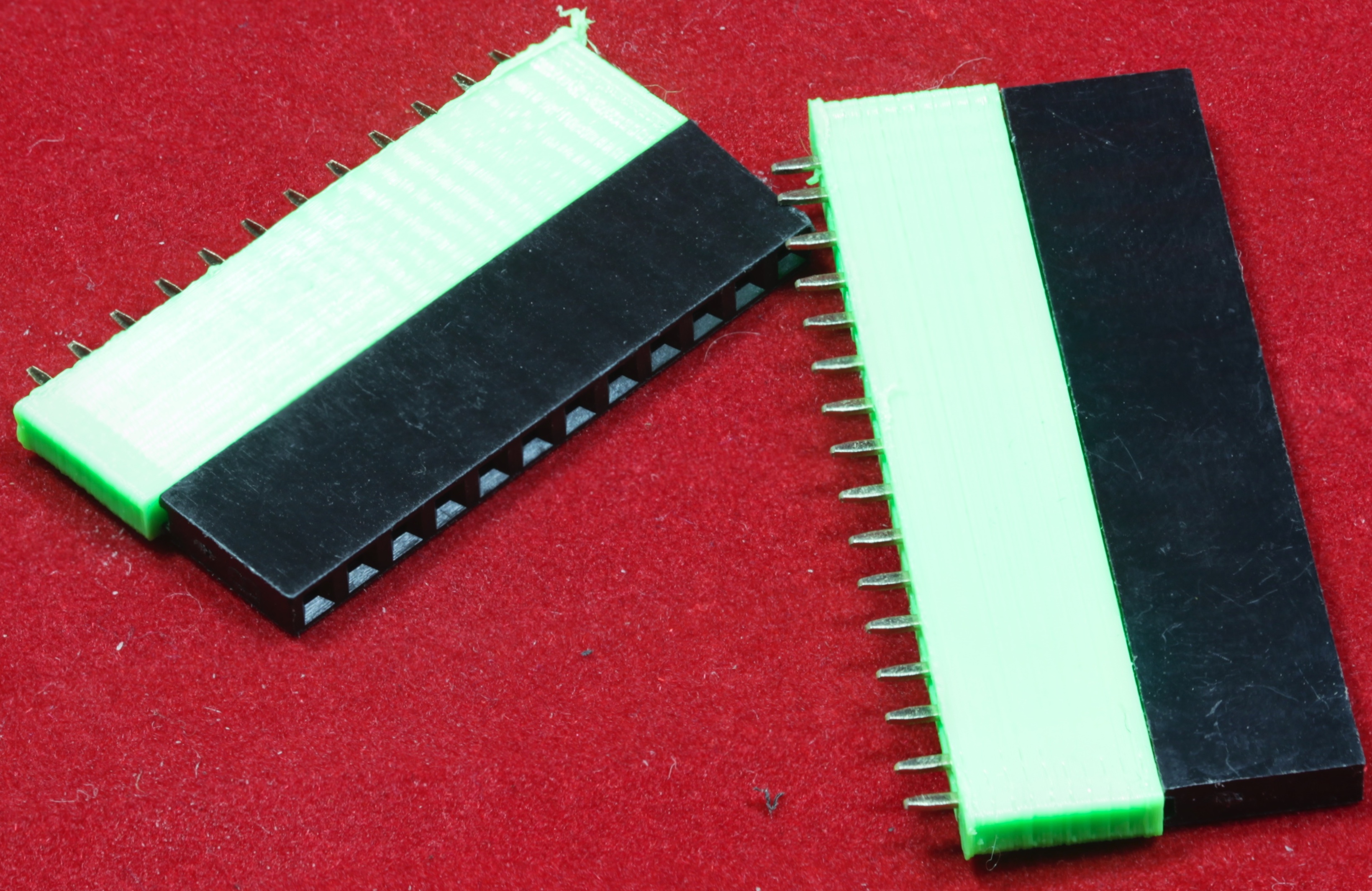
DIN Rail Mounts
The DIN rail mounts were created using AutoDesk's Fusion 360 (to produce STL files) and I personally print the results on a Lulzbot Taz6 3D printer using ABS filament (ABS is recommended for this job, PLA and PETG are a bit brittle).
There are three sets of DIN rail mounts:
- The "standard" Plantation Productions' DIN rail mounts. These work on most Plantation Productions' DAQ and EtherPort boards (3.5" x 5.9" / 90x150mm). There are two different mounts–one for the left side of the board and one for the right side of the board (the difference is how they tuck away the bulk of the mount underneath the PCB). These mounts have a fixed pair of arms that attach to the DIN rail. They are most easily slid onto the DIN rail from the end of the rail (if you're strong enough to bend the plastic, you can force them on or off in the middle of the rail). The EtherPort HCDOUT PCB attaches to the standard DIN rail mounts using a set of four 3/8" #3 wood screws (two for each mount).
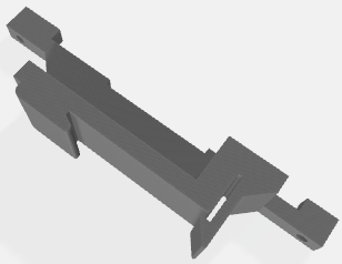
- The "adjustable" DIN rail mounts. These have an adjustable arm that latches onto the DIN rail. You tighten the arm down on a DIN rail using a 3/8" #3 wood screw. There is only a single version of this rail mount as it as two sets of holes to allow placement on either side of the PCB (the drawback is that certain boards may have through-hole pins that run into the plastic on the DIN rail as the interface area to the PCB is wider than the standard rail mounts). The EtherPort HCDOUT PCB attaches to a pair of adjustable DIN rail mounts using a set of four 3/8" #3 wood screws (two for each mount).
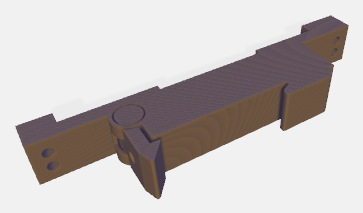
- The EtherPort HCDOUT vertical mount allows mounting the board vertically (rather than flat) on the DIN rail. This takes up less (horizontal) space than the standard and adjustable DIN rail mounts at the expense of not holding the board as rigidly. Also (obviously), the vertical mount requires more space above the DIN rail. One other disadvantage is that the vertical mount is specially designed for the EtherPort HCDOUT PCB and likely won't work with many other EtherPort or DAQ boards. The EtherPort vertical DIN rail mount also has an adjustable arm. The EtherPort HCDOUT PCB attaches to the vertical DIN rail mount using a pair of M3x20mm bolts and nuts (washers are also recommented).
The adjustable DIN rail (for 35mm DIN rails) as one arm that swings away for easily attaching to a 35mm DIN rail. You can tighten this arm down with 3/8" #3 wood screw. Note that it has a pair of holes on both sides so it can mount on the left or right side of an EtherPort HCDOUT board.
Adjustable DIN Rail Mount
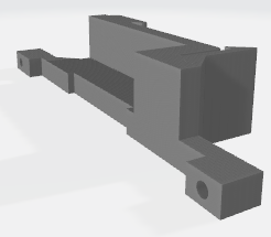
Standard DIN Rail Mounts (Left and Right)
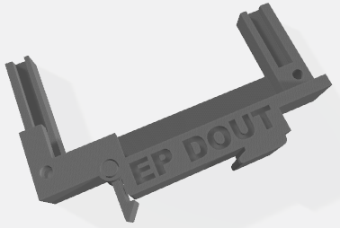
Vertical EtherPort DOUT mount (works for the EtherPort HCDOUT)
Revision History:
Rev 2:
Change LED resistor to 470Ω
Swapped pins on W5500A connector.
Added holes for Feather doubler.
Added test pins for RCK and SRCLR.
Moved TPIC6B595 ICs off the SPI bus and used separate I/O pins.
Fixed CS pins on Robotdyn Ethernet.
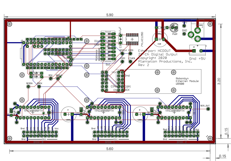
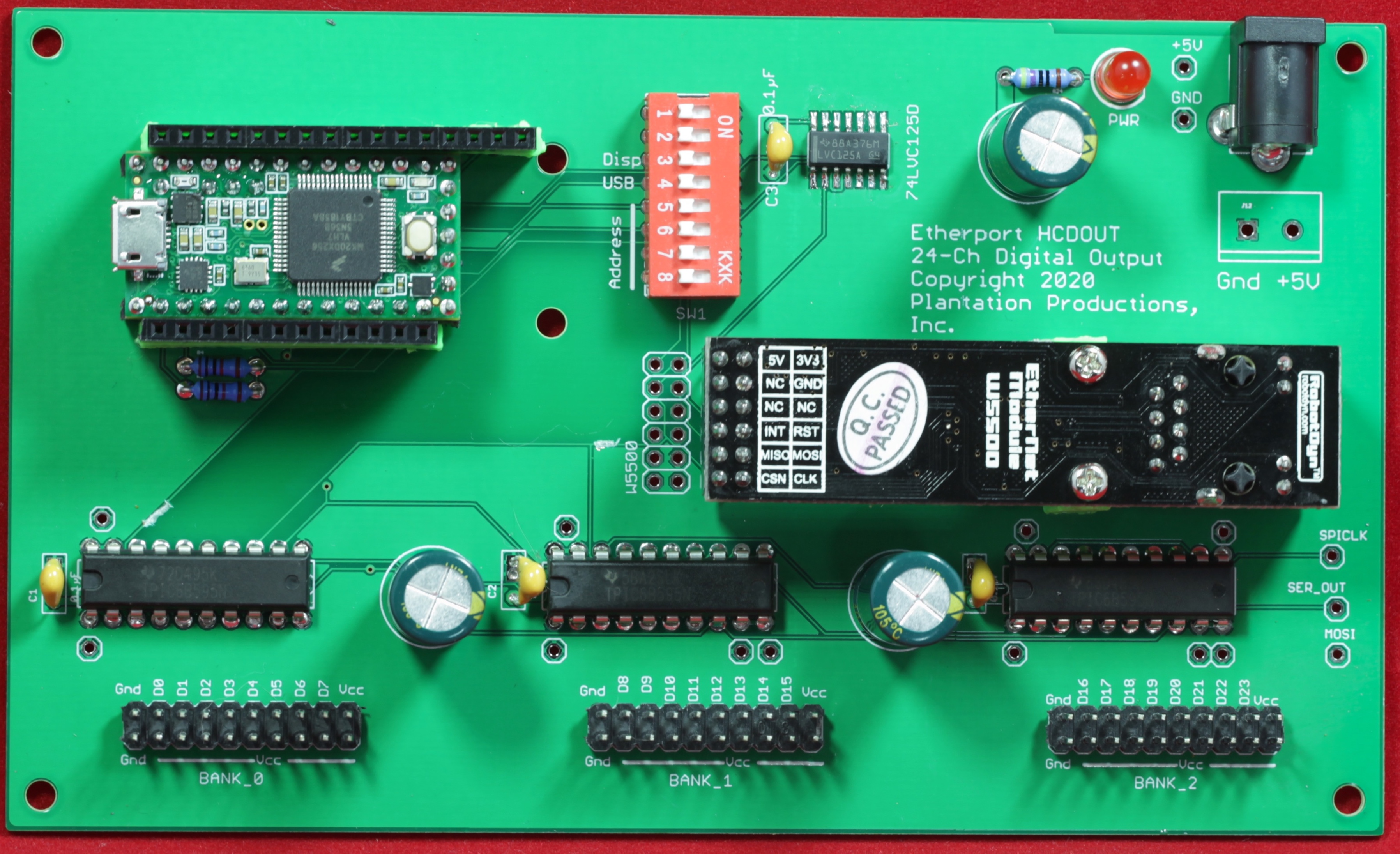
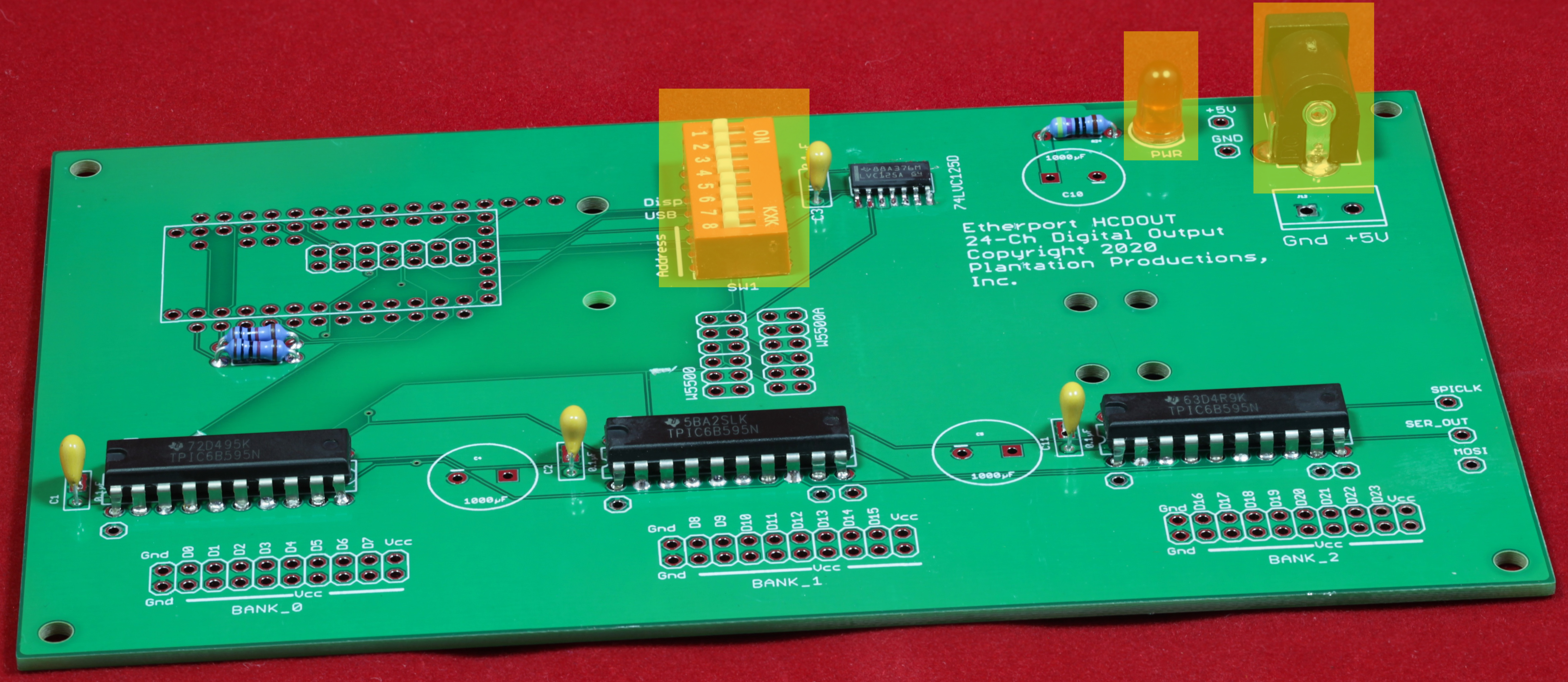
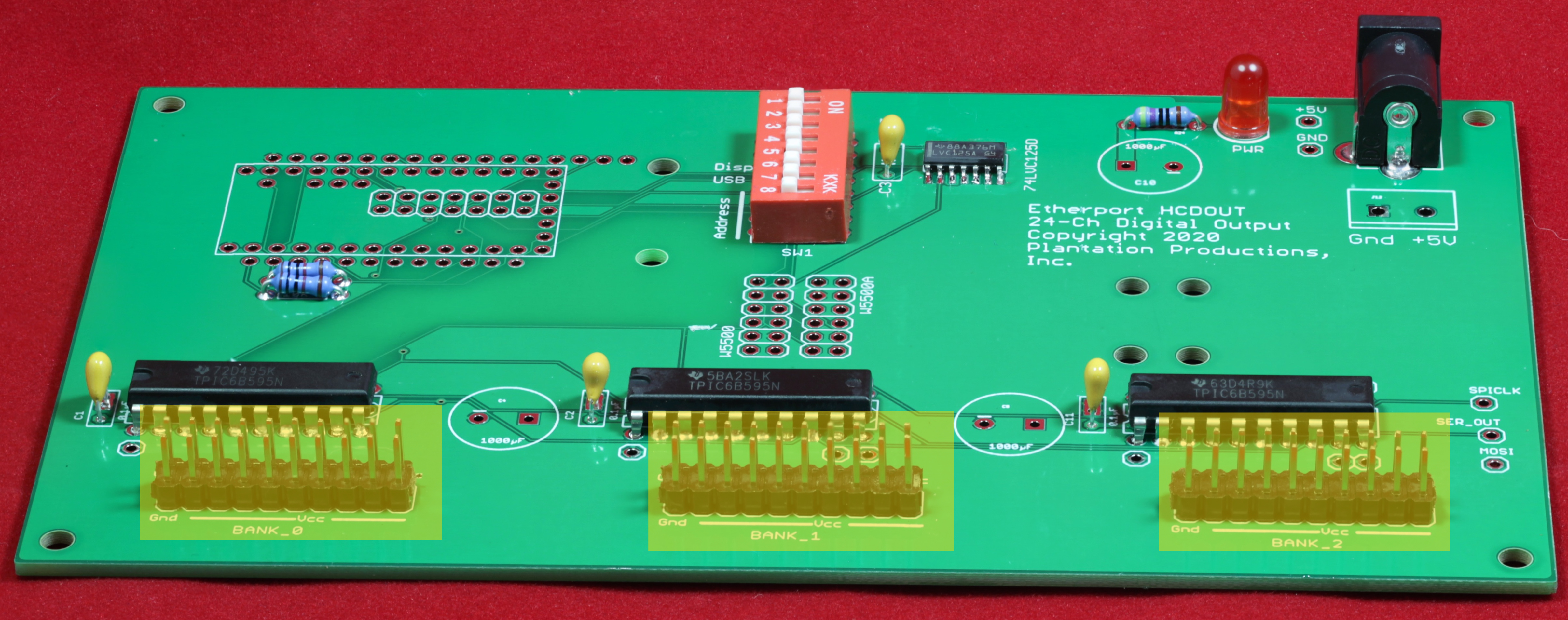
EtherPort HCDOUT Board Layout
Connecting Digital Outputs to the EtherPort HCDOUT Board
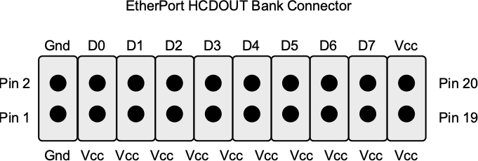
The 24 output lines on the EtherPort HCDOUT are broken up into 3 banks of 8 bits/bank. The connectors have the following pinouts:
Note, however, that the bit numbers are offset according to the bank number:
| Bank # | Starting bit # |
|---|---|
0 |
D0 |
1 |
D8 |
2 |
D16 |
So, for example, pin 18 for Bank 4 would actually be D23 (and pin 3 would be D16).
Because the digital outputs from the EtherPort HCDOUT aren't usually high-frequency signals (host system generally writes these inputs at around 10-20 Hz), their cabling requirements aren't very critical.
Although the tpic6b595 ICs used on the EtherPort HCDOUT run off a 5V power supply, the output pins can handle up to 50V (see the TPIC6B595 data sheet for more details).
Note that the TPIC6B595 ICs are open-drain devices. This means that the D0-D23 pins are high-impedance when a zero is programmed into the corresponding bit position, they are shorted to ground when a one is programmed into the bit position. Under normal circumstances, you would wire the high voltage (5v to 50v) to your load and the ground pin on your load gets wired to D0 through D23 on the EtherPort HCDOUT board. While a zero is programmed into the bit, no current flows through the load; when you program a one into the bit, this shorts the ground pin on the load to ground and current flows.
Pins 3, 5, 7, 9, 11, 13, 15, and 17 on the bank connector (that is, the pins opposite the data pins) are wired to +5v (Vcc). If you have a device that doesn't have it's down power supply, you can use the Vcc pin as the power supply pin for the load. For example, if you wire an LED (typically with a 470Ω resistor) to the Vcc and Dn pins (with the anode of the LED connected to Vcc and the cathode through the resistor to the Dn pin), then writing a one to Dn will turn on the LED, writing a zero will turn it off.
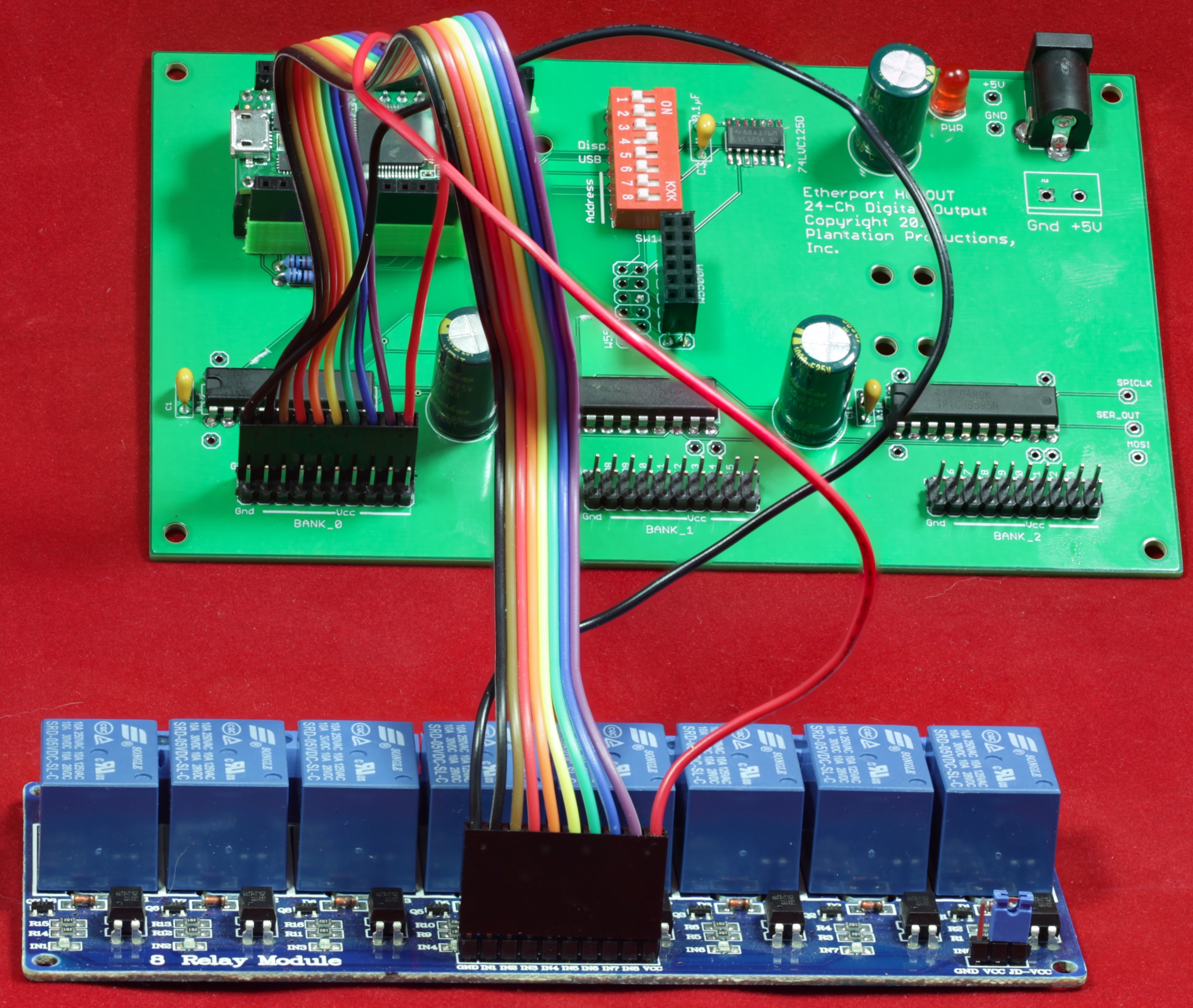
The ground and Vcc pins on either end of the Dn pins are intended for use with a SainSmart/JBtek/etc 8-channel relay (5v version). This is a very common (and inexpensive) board with eight relays (optically isolated). The 1x10 connector on the relay board has the same pinouts as the even pins on the HCDOUT bank connectors (technically, it's the HCDOUT that has the same pinout as the relay, as the relays existed first). If you need to control more than 50v or more than 150 mA, you can connect one of these relays to one of the output banks on the EtherPort HCDout for very high power control (the relays are typically rated at 250vac @ 10amps or 30vdc @ 10amps).
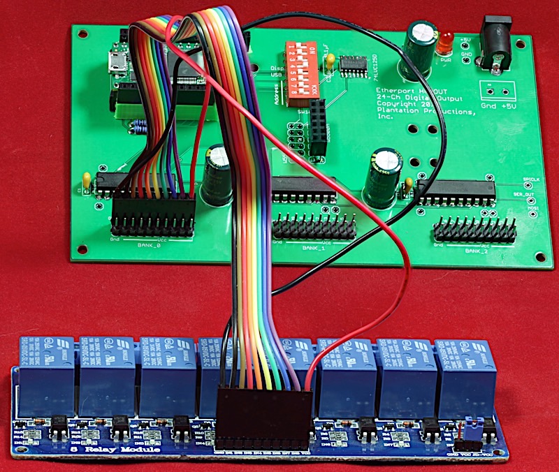
By the way, if you're wondering why the ribbon cable has separate wires for Vcc and Gnd, that's because typical ribbon cables are 28 AWG, which is too small for the current the relay board draws. Therefore, I wired up two 22 AWG solid-core wires for Vcc and Gnd to provide the necessary ampacity for the board. Note that it is also possible to wire up +5v and Gnd to the board on the little 3-pin header on the right-hand side of the relay board (in this picture).
Of course, if mechanical Form-C relays are too slow, too noisy (acoustically or electrically), or too unreliable for your requirements, you can also wire up the outputs from the EtherPort HCDout board to a set of solid-state relays.
DIP Switches on the EtherPort HCDOUT
The EtherPort HCDOUT board contains eight DIP switches, six of which connect to various input pins on the Teensy 3.2. This provides a convenient set of switches for setting default values and other options within your software. The standard software (and silkscreen markings) use these switches to set the Ethernet IP address and enable USB and an OLED display.
Test Pins on the EtherPort HCDOUT
The EtherPort HCDOUT board contains 10 test locations that make varous signals available to DVMs, Oscilloscopes, logic analyzers, and other devices:
- Serial in (to first tpic6b595)
- Serial out (from last tpic6b595)
- RCK (register clock signal)
- SRCK (serial shift register clock)
- SRCLR (serial shift register clear)
- Gnd
- Vcc (+5V)
You may optionally install test pins in each of these holes. A test pin allows you to clamp a test lead to the pin allowing hands-free circuit connection (otherwise you will need to press the test probe against the test signal's PCB pad).
Software Support for the EtherPort HCDOUT
The standard firmware can be found here:
The standard software can be configured to work with a Robotdyn W5500 Ethernet module or an Adafruit Ethernet Featherwing (this requires changing a single define in the source code). With a little bit of hackery, you could actually use both Ethernet modules, if you really had the need.
The standard firmware supports an Adafruit OLED Featherwing module (enabled by putting DIP switch 6 in the on position during power up). It also supports USB communication (in addition to Ethernet communication) by putting DIP switch 5 in the on position during power up.
The standard firmware is an Ethernet server application that waits for an Ethernet client to connect. It supports up to eight concurrent Ethernet clients (though usually there will be only one, maybe two during software testing). Once connected, the Ethernet client can send digital output values to the server or set different operating modes by sending lines of text (with commands) to the EtherPort HCDOUT and waiting for a response from the EtherPort HCDOUT.
The EtherPort HCDOUT server software accepts the following commands from the client (all commands are ASCII text terminated by a newline/linefeed character):
- dout xx yy zz
where xx, yy, and zz are two-digit hexadecimal numbers representing the bit pattern outputs for bank 0, 1, and 2 (respectively). Bit 0 of xx represents bit 0 on Bank 0 output pins; bit 7 of xx represents bit 7 of xx on Bank 0 output pins. Bit 0 of yy represents bit 0 on Bank 1 output pins; bit 7 of yy represents bit 7 of yy on Bank 1 output pins. Etc.
The dout command echos the input command as its response:
dout xx yy zz
If DIP switch 5 is in the on position on power up, then the EtherPort HCDOUT server firmware will also accept these commands from the USB port (which looks like a serial port on a typical host PC connected to the USB port).
Building a EtherPort HCDOUT Board
Note: the following instructions use Revision 1 PCB photos. There are largely only cosmetic differences between Rev 1 and Rev 2 PCBs plus the addition of a few more test pins.
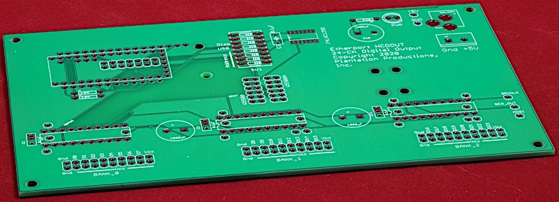
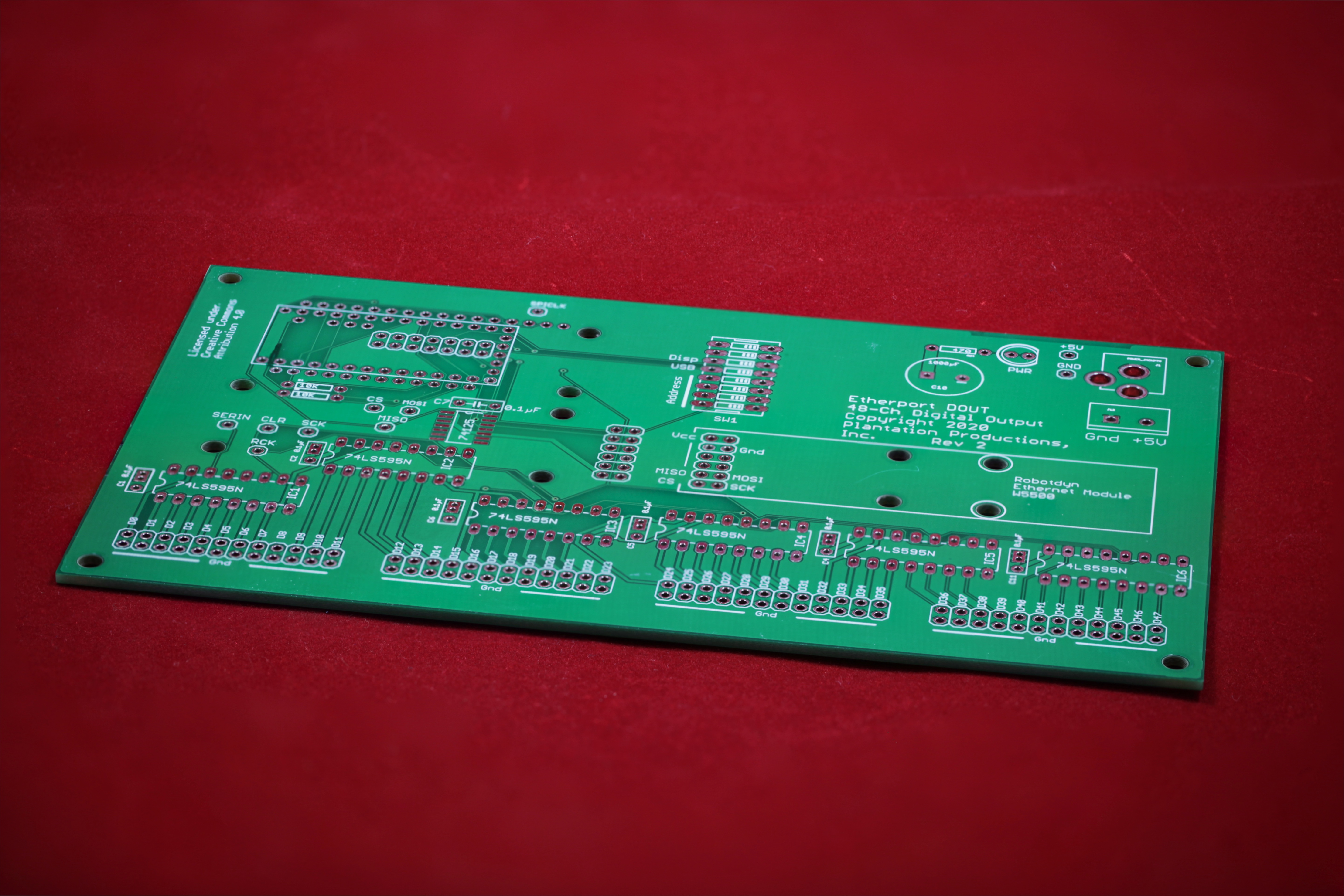
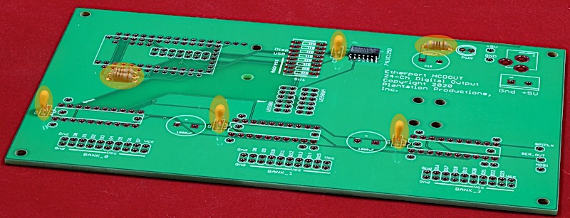
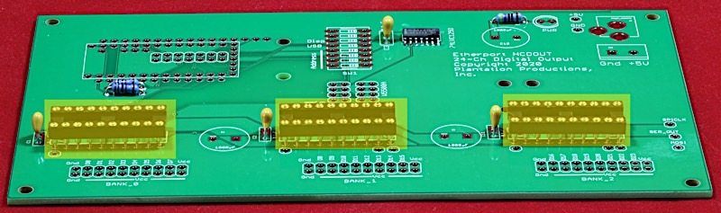
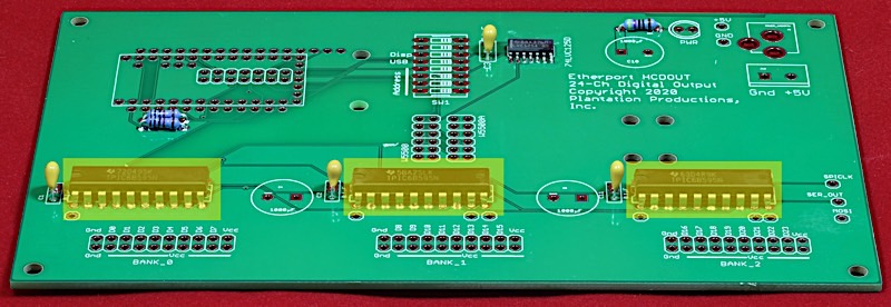
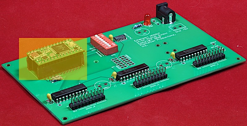
Here's the bare EtherPort HCDOUT PCB (printed circuit board):
Note: These assembly instructions show the assembly of the original PCB. The Rev 2 assembly instructions are mostly the same (a few test pins were added during Rev 2).
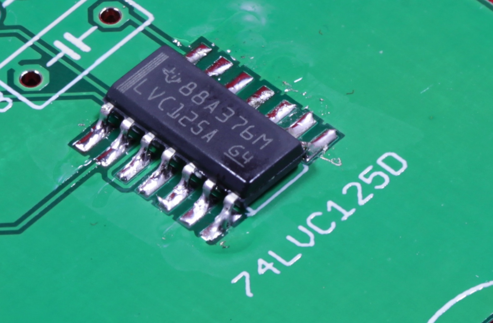
- The usual build process is to build a board from "the bottom up." This means to first install those items closest to the PCB and work you way up to larger objects on the PCB. So, the first thing to start with in the single SMT (surface mount technology) part on the board: the 74HC125 IC. Fortunately, this is an SOIC-14 package and it's possible (with care) to solder it onto the board with a standard (though fine-tipped) soldering iron. Begin by tacking one pin (pin 7 is a good anchor) down on the circuit board. Ensure the other pins are aligned properly on the pads and finish soldering the remaining 13 pins:
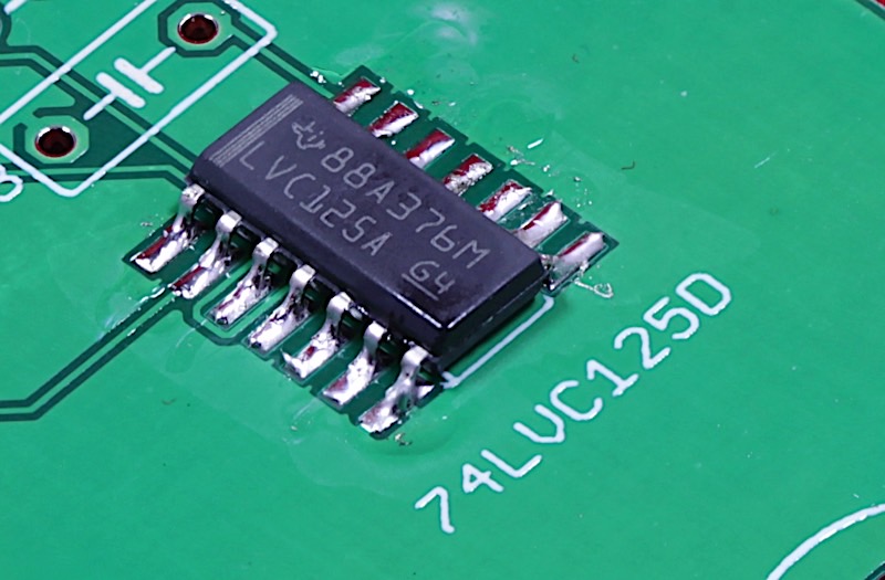
High resolution image
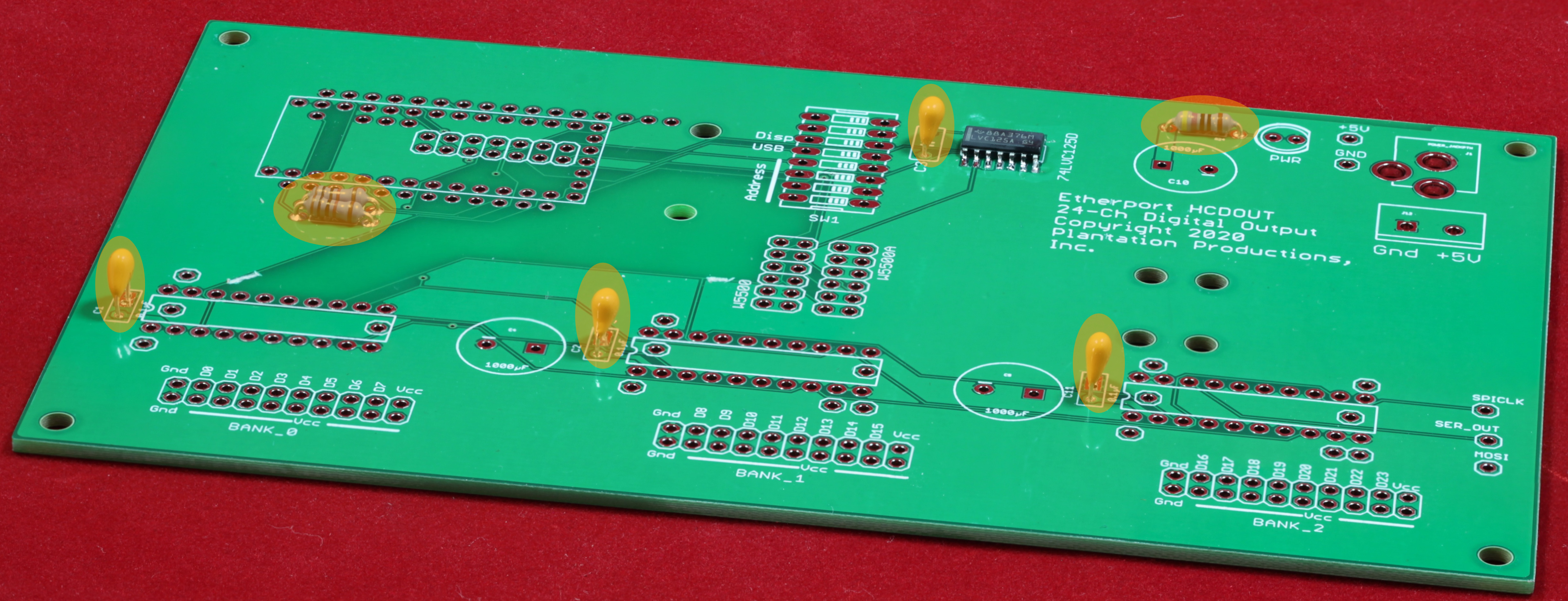
- Next, solder on the four 0.1µF bypass capacistors, the two 4.7kΩ resistors, and the 470Ω resistor:
High resolution image
- The next step is optional: install the seven test pins on the PCB. Generally, test pins are useful for testing initial runs of PCBs and while developing software for the board. However, for a production run, that than possibly connecting the ground test pin, you really don't need to install test pins. Though test pins could prove useful for field maintenance, it's easy enough to put a scope, logic analyzer, or DVM probe directly on the test pin pads.
Note: because the original PCB does not have the same test pins as the Rev 2 board, the assembly picture for this step does not appear here.
- The next step is also optional: install sockets for the ICs on the board. Sockets are optional. They make field repairs easy, but using sockets actually makes the board less reliable than soldering the ICs directly on the board (after several years, the contact between the IC pins and the socket gets corroded and the contact becomes intermittent; removing and reseating the IC usually solves this issue, but it’s a problem you don’t normally have when ICs are soldered directly to the board). If you do choose to use sockets, be sure to use high-quality ones (yes, high-quality sockets often cost more than the ICs going into them). Low-quality sockets create more problems than they solve. When installing sockets, be sure to insert them into the board with the notch on the socket matching the notch in the IC outline on the silkscreen.
Another issue to consider when socketing the TPIC6B595 ICs is thermal conductivity. The TPIC6B595 ICs generate a fair amount of heat when sinking a lot of current. The PCB acts as a heatsink to draw heat away from the IC. Socketing the ICs insulates them (slightly) from the PCB and reduces the thermal transfer. Therefore, I do not recommend socketing these ICs if they are going to have to control more than a few milliamps per pin (driving LEDs is probably okay, more than that, not so much).
High resolution image
Note: if you choose not to install sockets, you can solder the ICs onto the PCB at this point. Again, be sure to note the orientation of the chips based on the silkscreen images for the ICs.
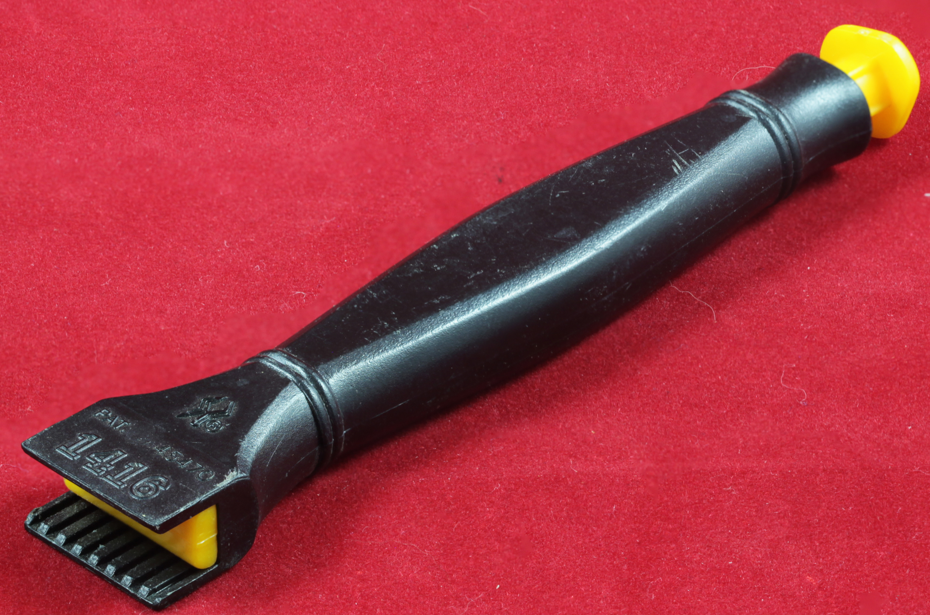
When inserting ICs, you will notice that the pins on the ICs are actually slanted outward and will not directly fit in the holes on the board (or in holes on the sockets, for that matter). If you have an IC inserter tool, it will automatically bend the pins to the appropriate position prior to insertion. If you don’t have such a tool available, just hold an IC with your fingertips with one row of pins against your workbench or desk and manually bend the pins until they are perpendicular to the body of the IC. Repeat for the pins on the other side of the IC.
IC Insertion Tool:
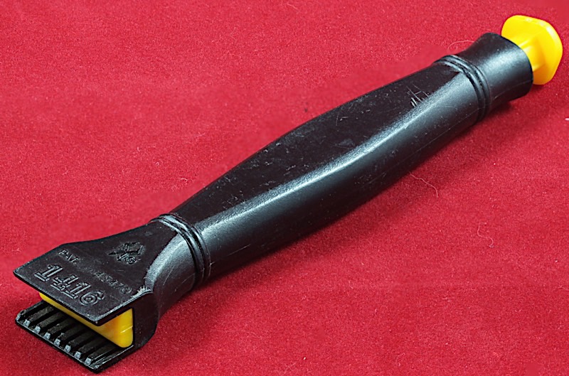
High resolution image
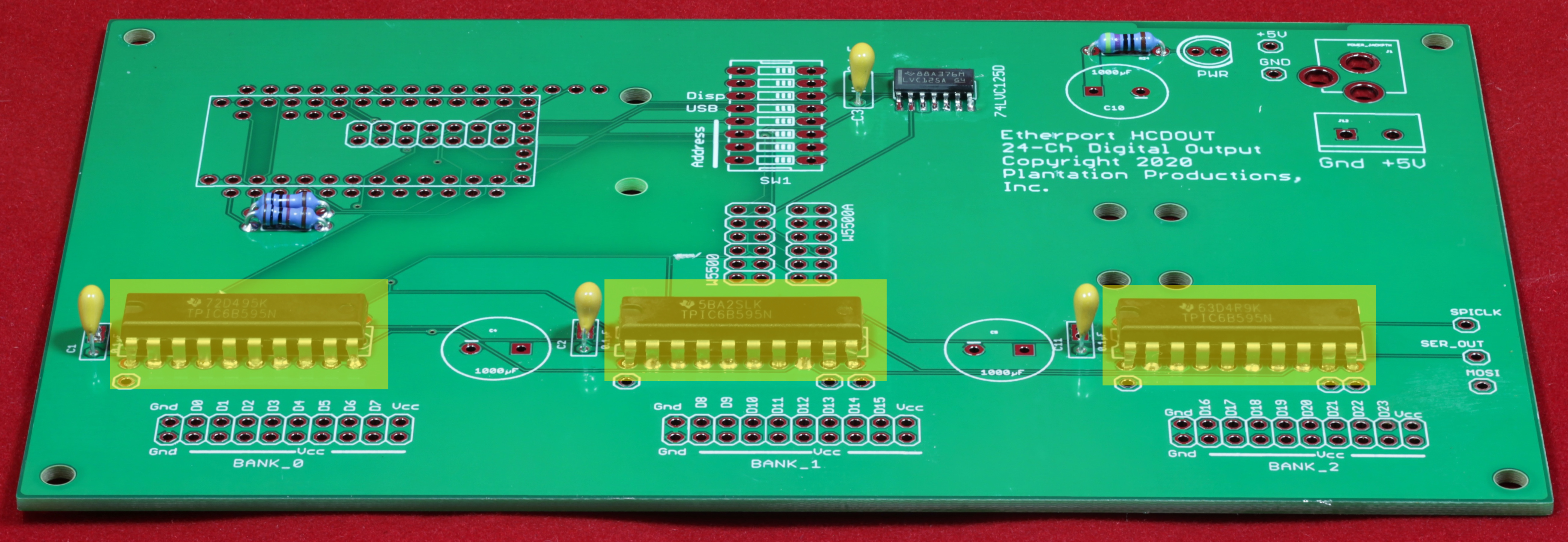
Board with ICs soldered directly to the PCB (this is the recommended assembly version):
High resolution image
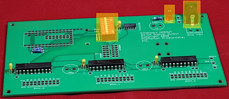
- For the next step, solder the LED, DIP Switch, and power connector onto the PCB. Note that the DIP switch should always be soldered directly onto the PCB; most DIP switches have pins that are too weak and shaped improperly to go into sockets. Besides, there’s not much to fail in a switch, so the likelihood you will need to ever replace it is low.
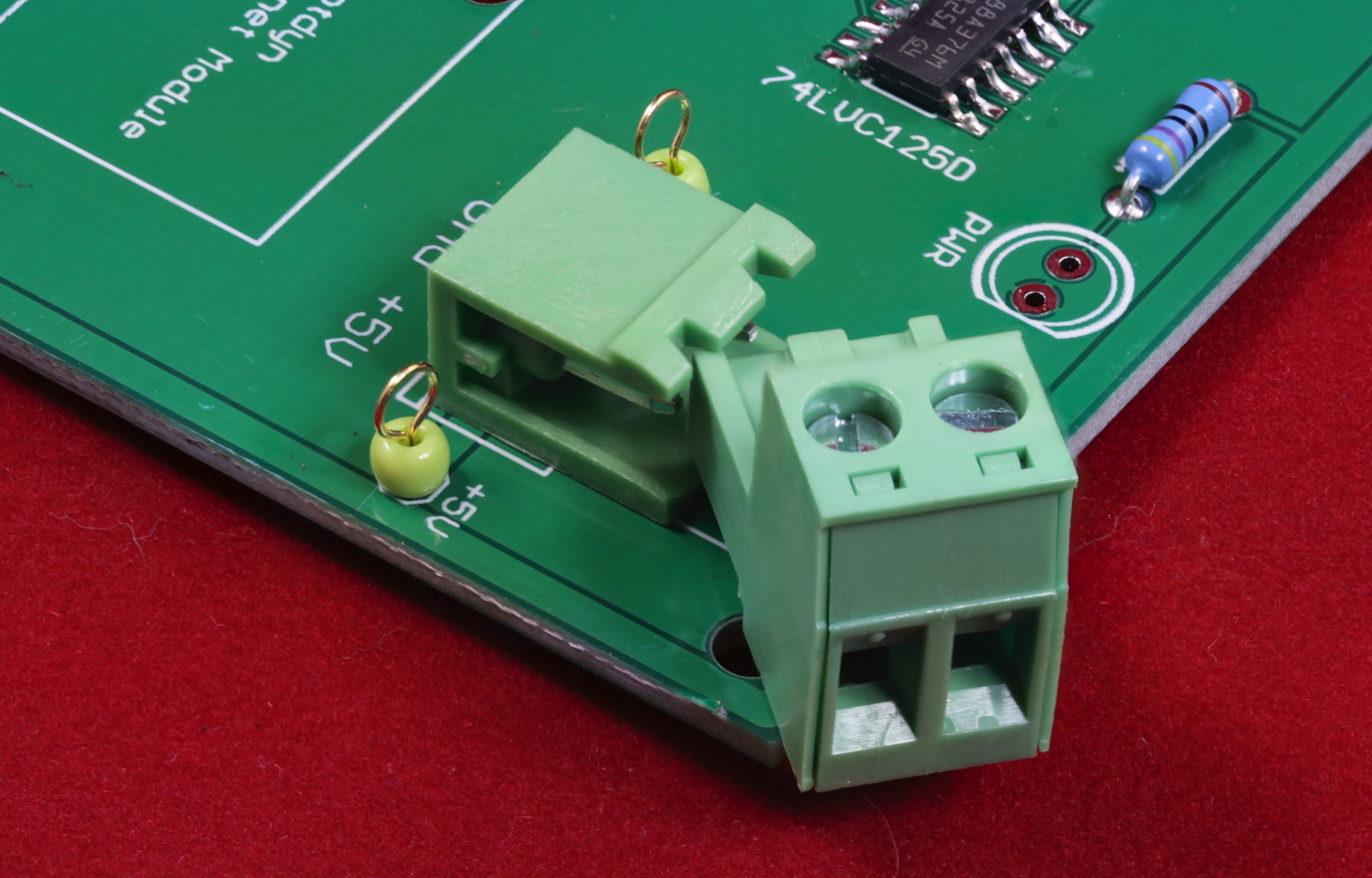
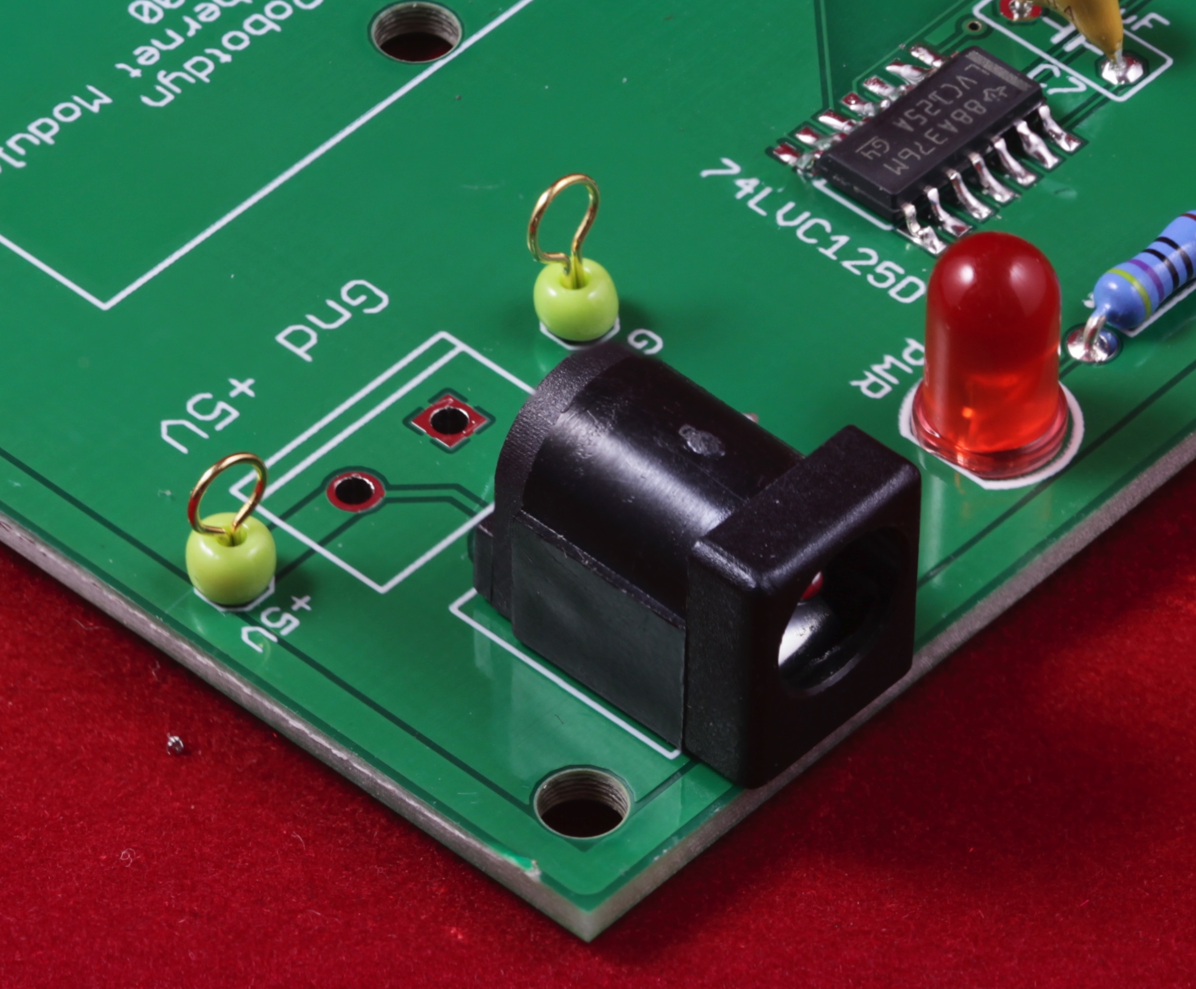
The EtherPort HCDOUT PCB provides two options for the power connector: you can either install a two-pin screw terminal (I prefer the higher-quality ones that have a removable screw terminal component—see the photograph), or you can install a 5.1mm barrel jack (center pin is +5v). Note that you should install only one or the other.
High resolution image
Example showing a detachable two-pin screw terminal (actually on an EtherPort DIN board, but terminal is the same)

High resolution image
5.5mm Barrel Jack (also on an EtherPort DIN board, but looks the same on EtherPort HCDOUT):
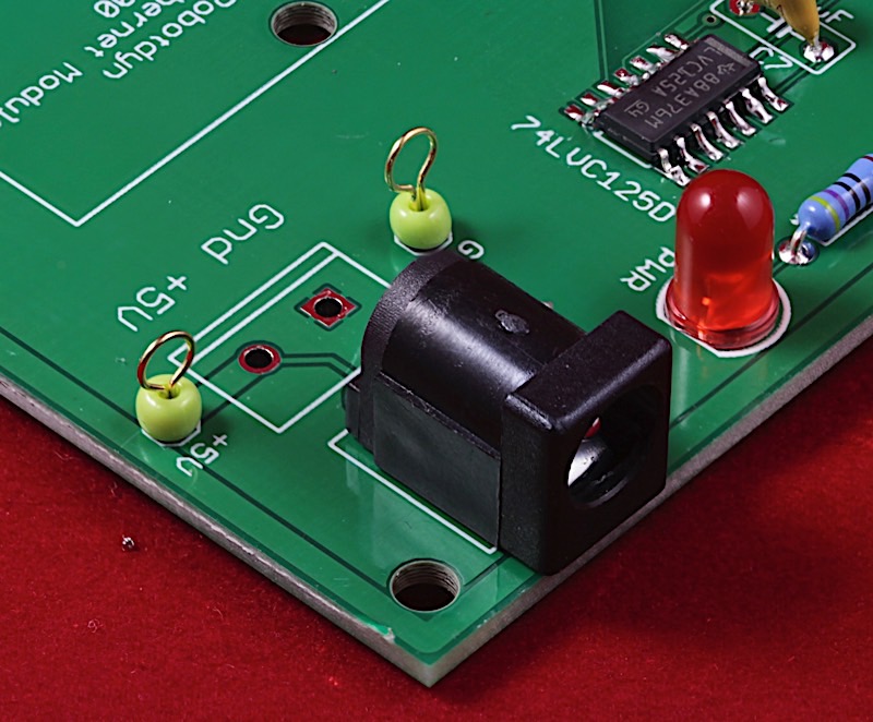
High resolution image
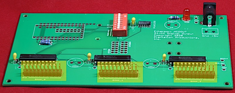
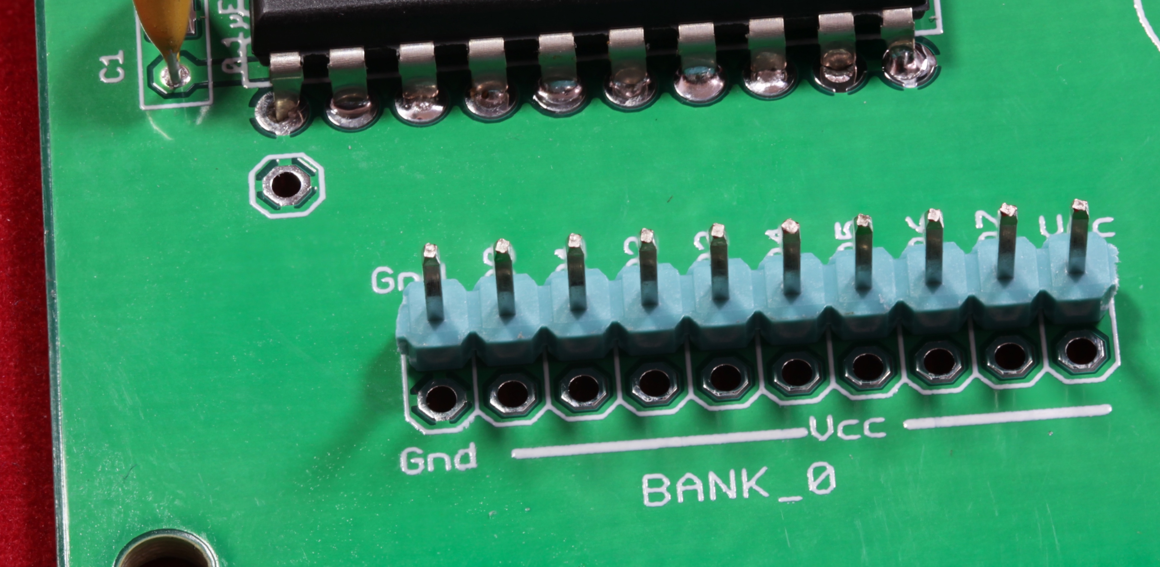
- The next step is to solder on the headers. There are two options here. If you are only going to attach an 8-channel relay board on one of the ports, you should probably install a 1x10 header (which is directly compatible with many relay boards, such as this one). Although the 2x10 header is completely compatible with the relay board as well (by simply inserting the cable on the top row of pins), there is less likliehood of installing the cable on the wrong row of pins if you install a 1x10 header header instead of the 2x10 header:

High resolution image
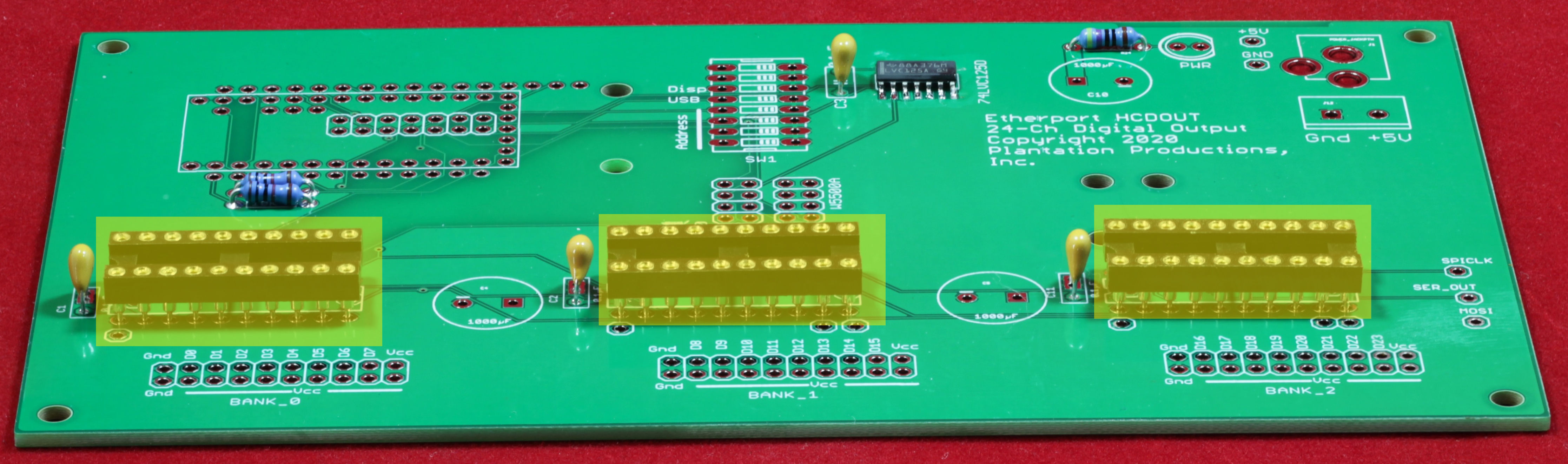
- Of course, the most general solution is to install the dual row headers. There are three 20-pin (2x10) headers:
High resolution image
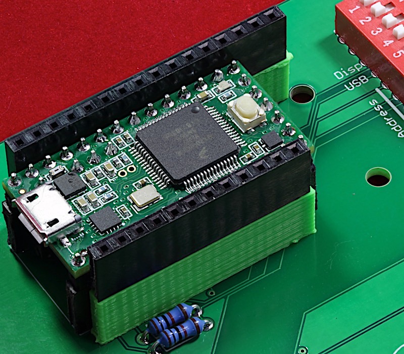
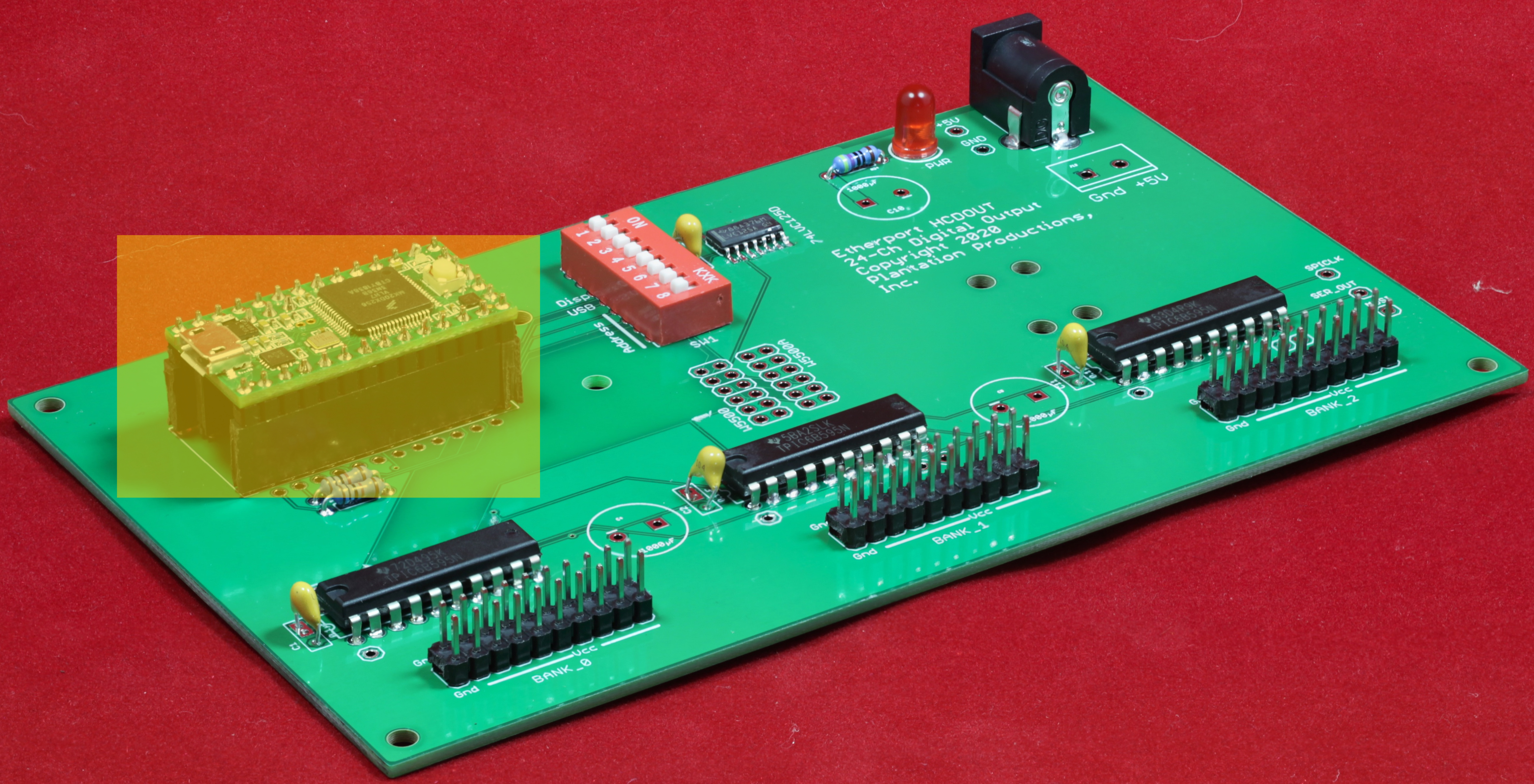
- Now, it's time to install the Teensy 3.2. The first step is to solder all the pins on the Teensy 3.2 (assuming you don't already have one prepared). The instructions for soldering all the pins on a Teensy 3.2 appear here. That web page also describes how to manufacture a socket for the Teensy 3.2 (a good thing to build, it's nearly impossible to remove a Teensy 3.2 from the EtherPort HCDOUT PCB if you soldered it directly onto the PCB; using a heat gun usually damages the Teensy).
High resolution image
- Now, it's time to install the Feather Bus headers. These are a pair of 1x12 and 1x16 female headers with long leads. You can get them from Adafruit or chop up a set (if you don't find the exact length you need) from longer ones purchased on Amazon (or elsewhere). The Feather bus headers need to raise the Featherwing above the Teensy 3.2. The Adafruit headers (which I'm pretty sure are a standard height) just barely clear the Teensy installed in a socket, leaving just enough pin length in the hole to solder them onto the PCB. The real problem is getting them soldered on in a level manner (especially the same level on both sides of the Teensy). To make this task easier, I've created a pair of shrouds (standoffs) that I've 3D printed into which I insert the pins of the headers. Find the 12-pin shroud here. Find the 16-pin shroud here.
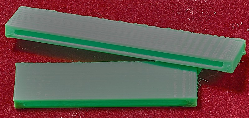
High-resolution image

High-resolution image
- Insert the 1x12 and 1x15 Feather bus headers into the shrouds and insert them into the appropriate holes on either side of the Teensy 3.2. I generally insert some Featherwing into the headers to hold them at the right position while I solder the headers to the PCB:
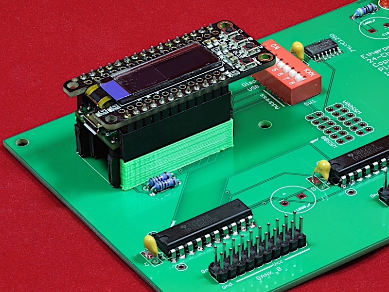
High-resolution image
- After tacking down opposite corners of the Feather bus headers, turn the board back over and verify that the headers are evenly pressed into their holes, then finish the soldering of the remaining pins.
High-resolution image
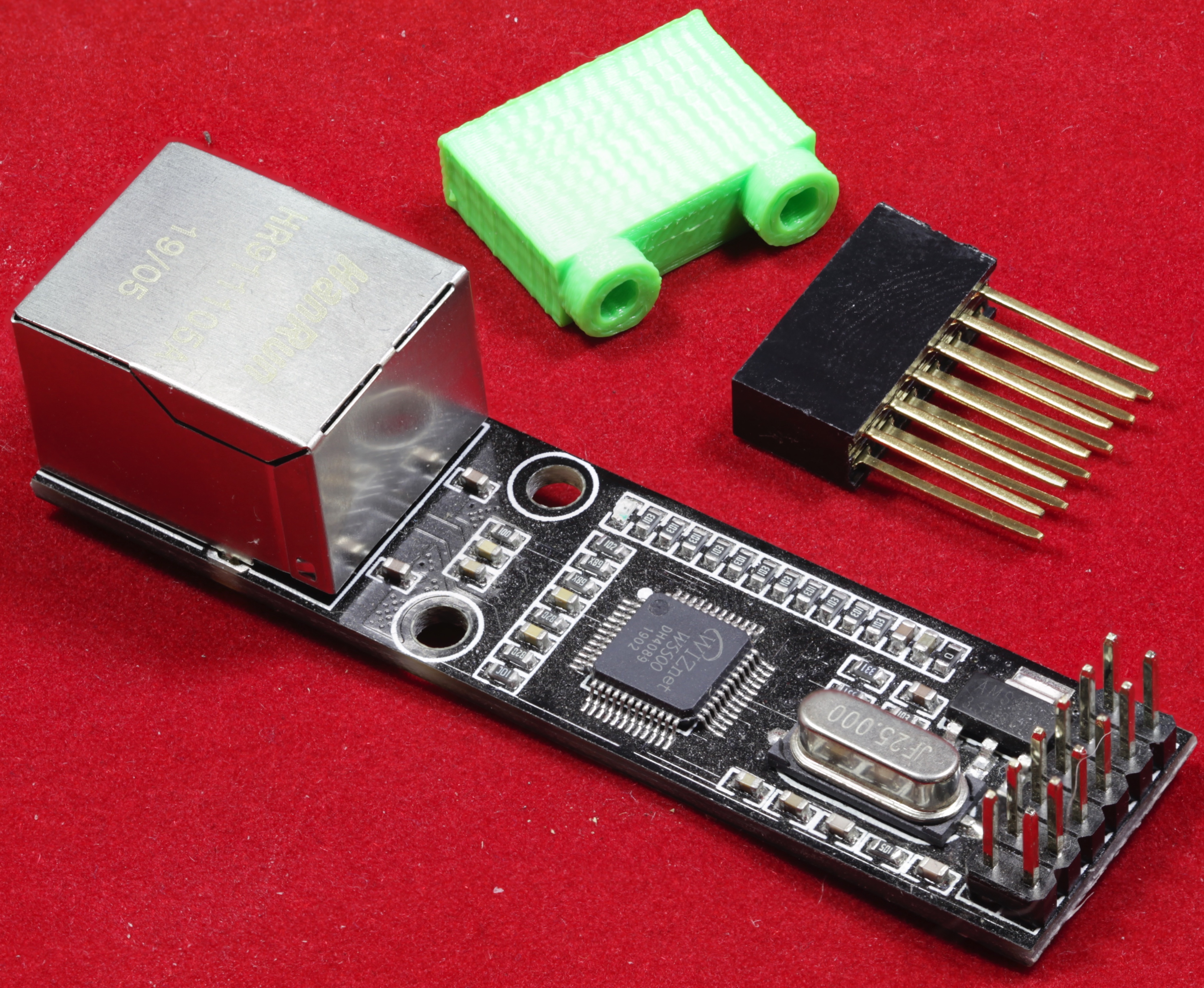
- Next you have to decide whether (1) You will use Ethernet communications on the board (despite the name, Ethernet is optional; you could just use USB), and (2) if using Ethernet, which interface will you use. There are two "standard" Ethernet interfaces you can use with the EtherPort HCDOUT: An Adafruit Etherwing board (that plugs into the Feather bus headers) or a Robotdyn W5500 Ethernet module. The Adafruit unit is a lot more reliable in my experience, the Robotdyn unit is 1/3 the cost. In reality, you can hook up any 5v W5500 Ethernet module to the EtherPort HCDOUT board. The SPI bus lines come out to the 2x6 connectors on the board and there are even four mounting holes into which you can screw a 3D printed bracket for your own module (you could even run a 3.3v unit by running a wire from the Feather/Teensy 3.3v output to your module). However, this assembly tutorial will assume you're attaching a Robotdyn or Adafruit Etherwing module.
Robotdyn W5500 Ethernet module:
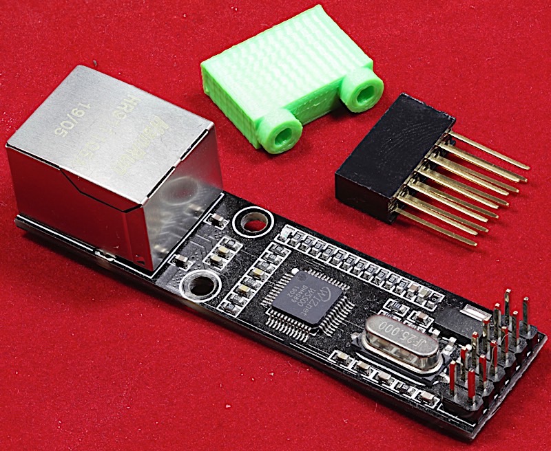
High-resolution image
Note: The STL file for the 3D printed bracket for the Robotdyn W5500 Ethernet module can be found here. You attach the bracket using four #3 3/8" wood screws (two for the Robotdyn board, two for the EtherPort HCDOUT PCB).
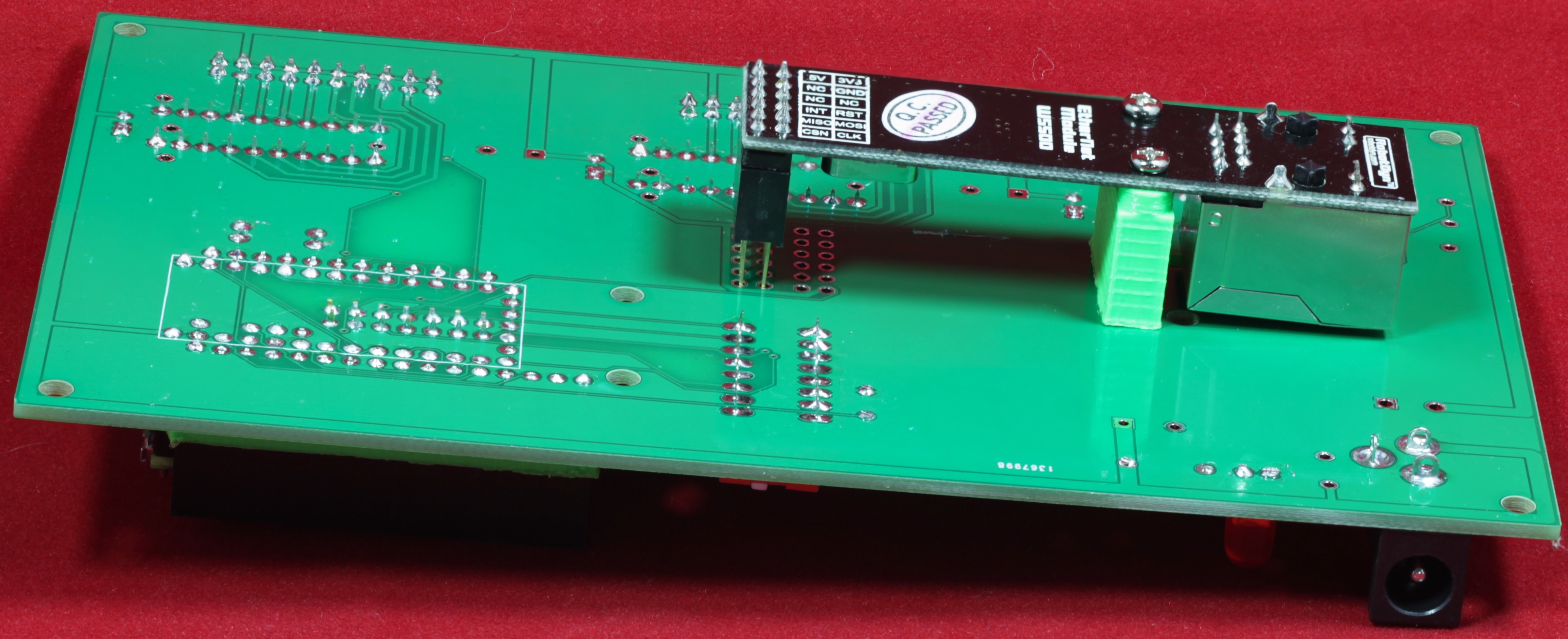
- If connecting a Robotdyn W5500 Ethernet module, you have two choices: you can mount the module on the top of the board or the bottom of the board. Note that on the Rev 2 board, the two connectors are separated slightly more and there are silkscreen legends showing the position of the Robotdyne unit on the top or bottom of the PCB. Here it is mounted on the bottom:
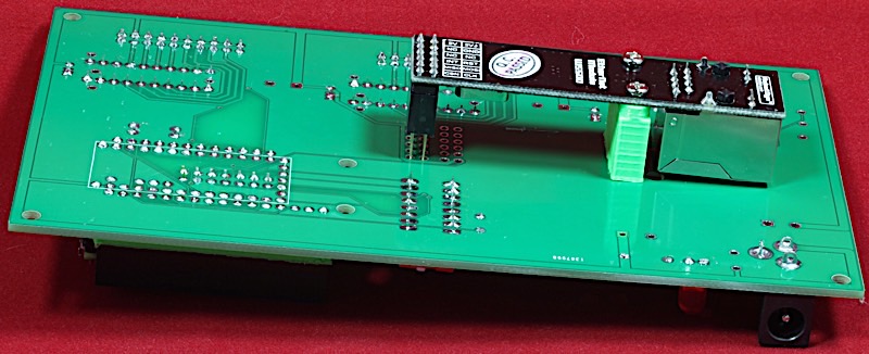
High-resolution image
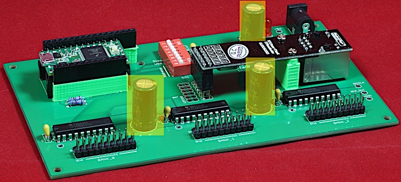
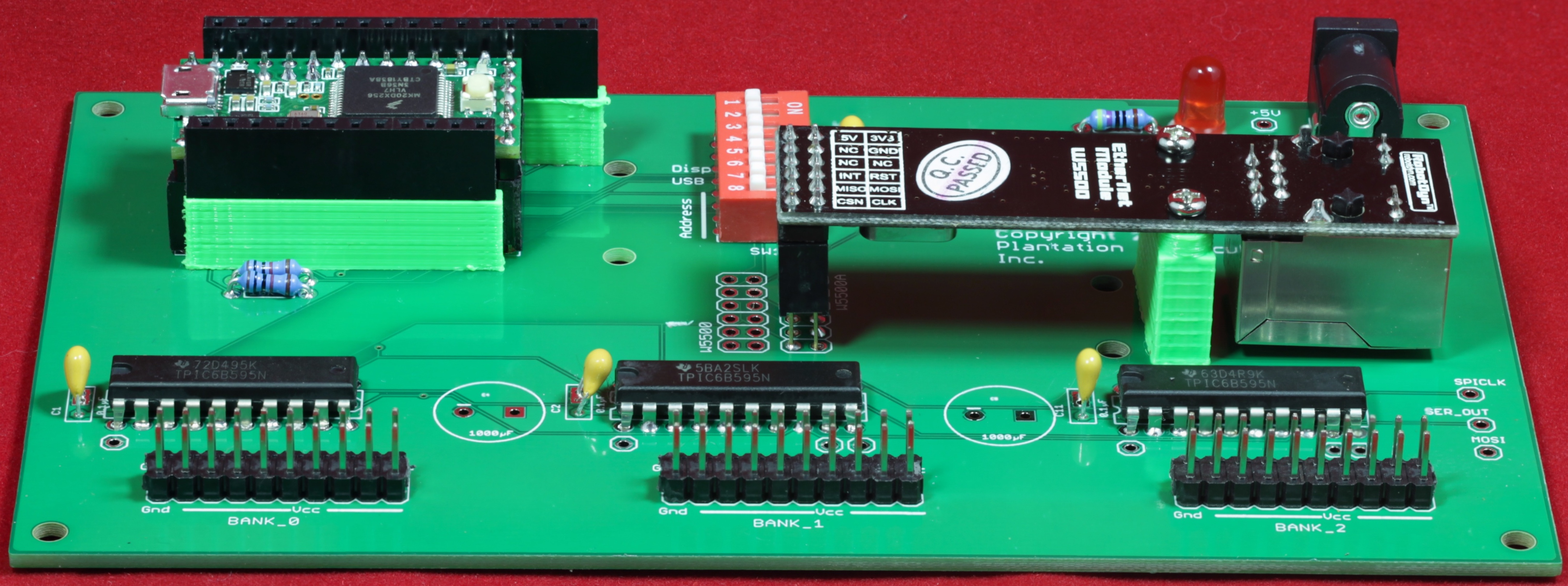
Here it's mounted on the top (the typical mount point):

High-resolution image
You can also install an Adafruit Etherwing on the Feather bus connector rather than the Robotdyn module.
- Finally, install the 1000 µF capacitors:
High-resolution image
- At this point, soldering is largely complete (assuming you’ve made no mistakes that will require some rework). Turn the board over and slowly, careful, visually inspect every solder joint. Well over 50% of the failures I’ve had were due to missing a solder connection. It’s worthwhile to visually inspect all the pins (yeah, I know, there are a lot of them) to verify you haven’t missed any.
High-resolution image
- Now for the actual “smoke” test. With the ICs inserted, apply power and make sure the LED still lights up (no flickering!) and nothing gets overly hot (or worse, smokes and catches on fire! Yes, this has happened to me in the past).
Testing the EtherPort HCDOUT Board
- Assuming your board passes the “smoke” test, now it’s time to do a real test on the board. This will require running software on the EtherPort HCDOUT board. Testing is done using the standard firmware for the EtherPort HCDOUT.
- To test the HCDOUT directly from the Arduino IDE, be sure to set the "USB" DIP switch in the on position.
- Note that the program simply checks the functionality of each of the output pins, it does not verify the operation of the Ethernet port (though you could use an Ethernet terminal program to program the outputs). It does check the function of the USB port as the program writes the output to the Arduino/Teensyduino serial output display and reads commands from the serial input.
- To test the individual output bits, hook up a device (such as one of the 8-channel relay boards described earlier, or an LED with a 470Ω resistor connected to each output bit and +5v line). Use the "DOUT x y z" command with the following outputs: "1 0 0", "2 0 0", "4 0 0", "8 0 0", 10 0 0", "20 0 0", "40 0 0", "80 0 0", "0 1 0", "0 2 0", "0 4 0", "0 8 0", "0 10 0", ..., "0 0 80" to individually test each of the output bits.
- To test the Ethernet port, use an Ethernet terminal program. I've always used the Hercules terminal program. Running it, I can type all the EtherPort HCDOUT commands ("dout", "reset", and "refresh") and check their operation.
Hardware Design Description
The hardware design for the EtherPort HCDOUT board is relatively straight-forward. Three TPIC6B595 serial-to-parallel shift registers are wired in series are connected to the Teensy 3.2. Pin 2 from the Teensy drives the SRCK (shift register clock) inputs on the TPIC6B595s. The TPIC6B595 SRCLR (clear) pin is driven by pin 31 on the Teensy. The RCK (register transfer clock) input is driven by pin 32 on the Teensy. Pin 7 on the Teensy connects to the serial input pin on the first TPIC6B595 in the shift register series. The SER_OUT line on the first and second 74HC595 ICs (the unlatched serial output signal) connects to the serial input of the next TPIC6B595 in the series.
The Robotdyn W5500 Ethernet Module will actually work off 5v or 3.3v. However, to avoid problems the EtherPort HCDOUT board only runs 5v to the connector for this device. The MOSI, chip select (pin 29), and clock pins are all 3.3v going to the Ethernet module (which is fine, that's still TTL compatible). The MOSI signal coming back from the Robotdyn board has to be level shifted from 5v down to 3.3v (also using one of the channels on the 74LVC125 IC). You can wire up a different W5500-based Ethernet board to the EtherPort HCDOUT; the +5v, Gnd, MOSI, MISO, SCK (SPI-CLK), and CS lines are clearly labelled next to the holes on the EtherPort PCB. You could even run a 3.3v version by running a jumper wire from the 3.3v output on the Teensy 3.2 to the power supply on your device (running the 3.3v output through the 74LVC125 won't matter). Two sets of W5500 connectors were placed on the board to allow mounting the Ethernet module on the top or bottom of the board.
As a general rule, Plantation Productions' DAQ and EtherPort boards attempt to use through-hole ICs and parts. SMT devices are usually put on breakout boards so they can be (more) easily removed from a PCB, if necessary. The 74LVC125, sadly, is only available in an SMT package (SOIC-14 for the variety used on the EtherPort HCDOUT board). Because the IC is so cheap (well under a dollar), and it's still easy enough to hand solder, the 74LVC125 was put directly on the EtherPort HCDOUT PCB. If you need to remove it, a localized hot-air gun, or better yet a Chip Qwik SMD removal kit, will take it off.
The Feather bus on the EtherPort HCDOUT is primarily intended for the Adafruit Ethernet Featherwing board (assuming a Robotdyn W5500 Ethernet module is not used). Two "canned" solutions for Ethernet were designed into the EtherPort HCDOUT board because Robotdyn modules, being rather inexpensive, haven't always worked. The Adafruit Ethernet Featherwing, on the other hand, has never not worked. The Feather bus also supports the Adafruit OLED Featherwing display module. The design includes four extra mounting holes for a Featherwing doubler, in case the need arised to install both an OLED display and an Ethernet Featherwing. Other possible Featherwing modules, such as the data logger or real-time clock, are generally stackable; therefore, no attempt was made to allow the installation of anything bigger than a doubler.
On most EtherPort boards (including the HCDOUT), every attempt is made to leave the general-purpose analog and digital I/O pins unused. Except for the SPI and I2C bus pins (SDA, SCL, MOSI, MISO, and SCK) the Feather bus pins are left alone for Featherwings (wherever possible). For digital I/O lines, the EtherPort HCDOUT uses the non-Feather I/O pins found on the Teensy 3.2.
Note: on power up, the output values on the TPIC6B595 (output) pins are undefined. The standard firmware immediately clears the output registers on bootup. If you write your own firmware for the EtherPort HCDOUT, you should also clear all the output bits on power up.
Software Design Notes
The standard firmware running on the has a couple of important defines and variables that must be set when compiling the code:
- #define EthCS (xx): This should be set to either "(cs)" (for an Adafruit Ethernet Featherwing) or to "(W5500CS)" (for a Robotdyn W5500 Ethernet module). If you wire up a different module, you should also use the "(W5500CS)" define and use the chip select (pin 29) set aside for the W5500.
- #define baseIP2ndB 2: The EtherPort HCDOUT responds to IP address 192.168.x.y. The x byte is specified by the baseIP2ndB define (default is 2). If you want to change this to some other value, change the define for baseIP2ndB. Note: most Plantation Productions' software expects the second byte to be 2. Think carefully before changing this value as you might make the EtherPort HCDOUT firmware incompatible with other Plantation Productions' devices and firmware.
- #define baseIPadrsLOB 30: The low-order byte of the IP base address defaults to this value (30 is the standard default). Note that the firmware reads DIP switches 1 through 4 and adds this 4-bit value to the LO byte. This allows multiple EtherPort HCDOUT boards in the system (without modifying the firmware). Because it's possible to enter 15 on the DIP switches, the default LO base byte value must be 240 or less.
- #define usbDebug 0: This define should be 0 for standard firmware builds. If it is non-zero, then the firmware writes debug information to the Arduino Serial device (i.e., the USB port) during operation. For testing purposes, this output is useful. However, if you've enabled the USB port for host communication purposes, this debug information may interfere with the operation of the host software.
- Note that when shifting data out to the shift register, the system must shift the most significant bit (bit 23) first and the least significant bit (bit 0) last. The EtherPort HCDOUT hardware implements a software shifting scheme using I/O pins on the Teensy, it does not use the SPI pins for this purpose. The following is the code for shifting out a bit, byte, and 24 bits to the EtherPort HCDOUT output pins (as well as a function that clears all the output bits):
// shiftBit-
//
//  Writes 8 bits to the TPIC6B595 ICs:

void shiftByte( uint8_t byte )
{
    for( int i=0; i<8; ++i )
    {
        digitalWrite( SERIN_7, !!(byte & 0x80) );
        byte <<= 1;
        digitalWrite( SRCK_2, 0 );
        digitalWrite( SRCK_2, 1 );
        digitalWrite( SRCK_2, 0 );

    }
}

// write24
//
//  Writes 24 bits to the TPIC6B595 ICs

void write24( uint8_t byte2, uint8_t byte1, uint8_t byte0 )
{
    shiftByte( byte2 );
    shiftByte( byte1 );
    shiftByte( byte0 );
    digitalWrite( RCK, 0 );
    digitalWrite( RCK, 1 );
    digitalWrite( RCK, 0 );
}