
Note: All photographs appearing on this page are freely usable for any purpose. Links to high-resolution versions of the pictures appear below each picture.
Ethernet/USB-based Watchdog Timer and Expansion Board
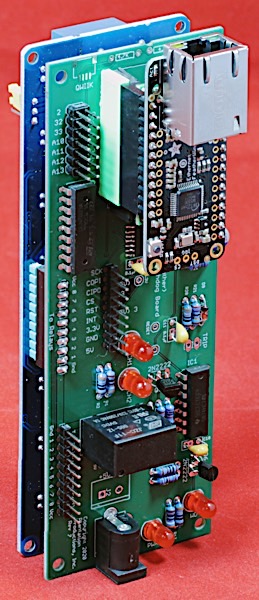
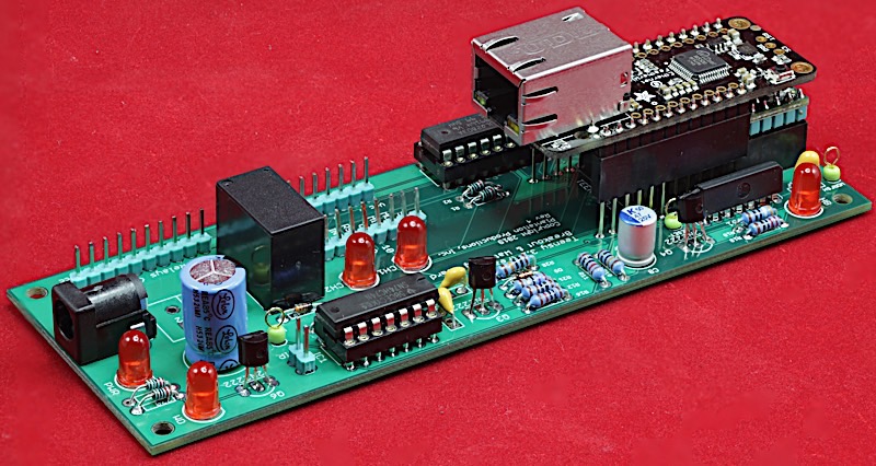
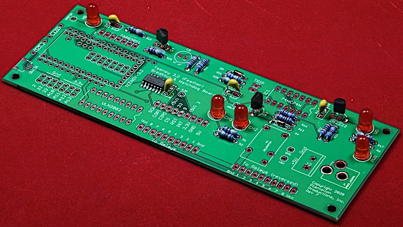
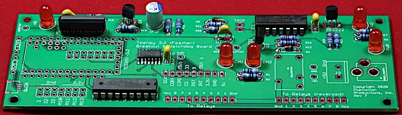
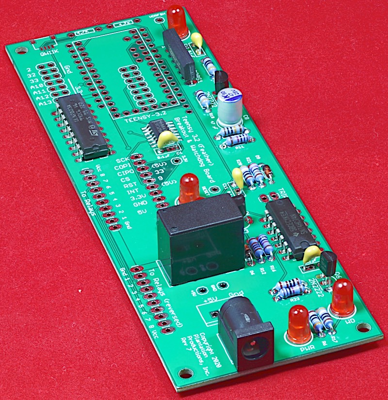
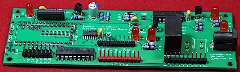
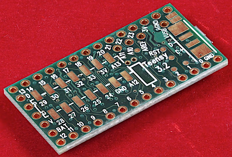
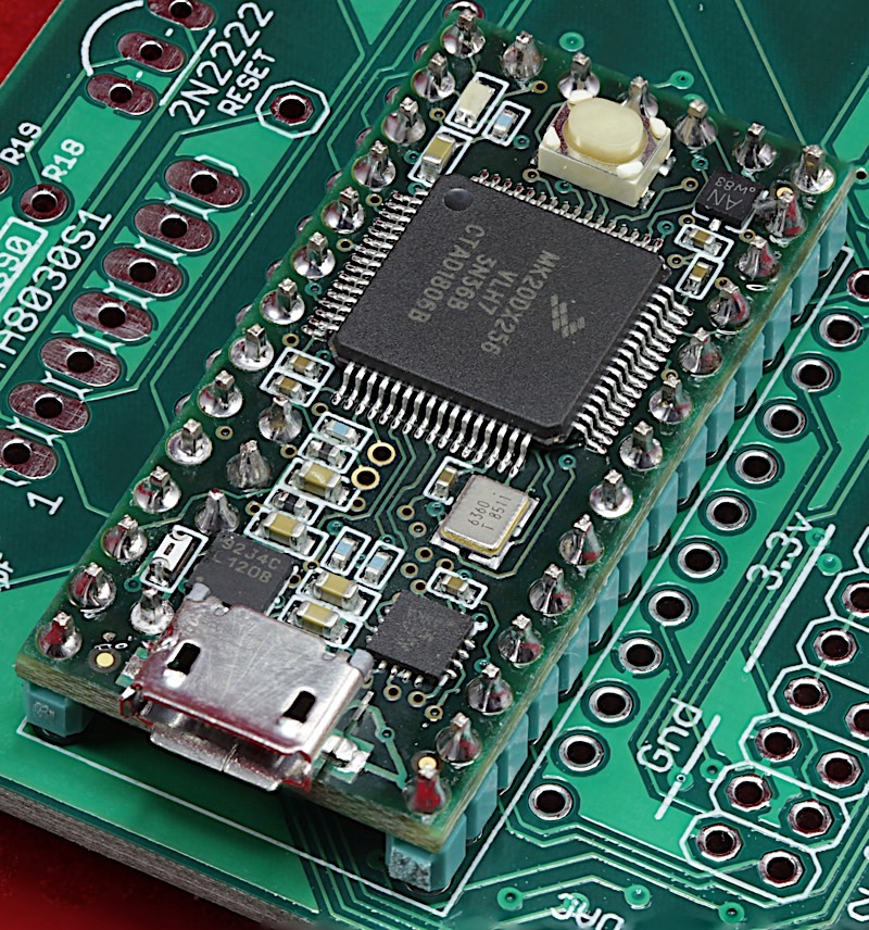
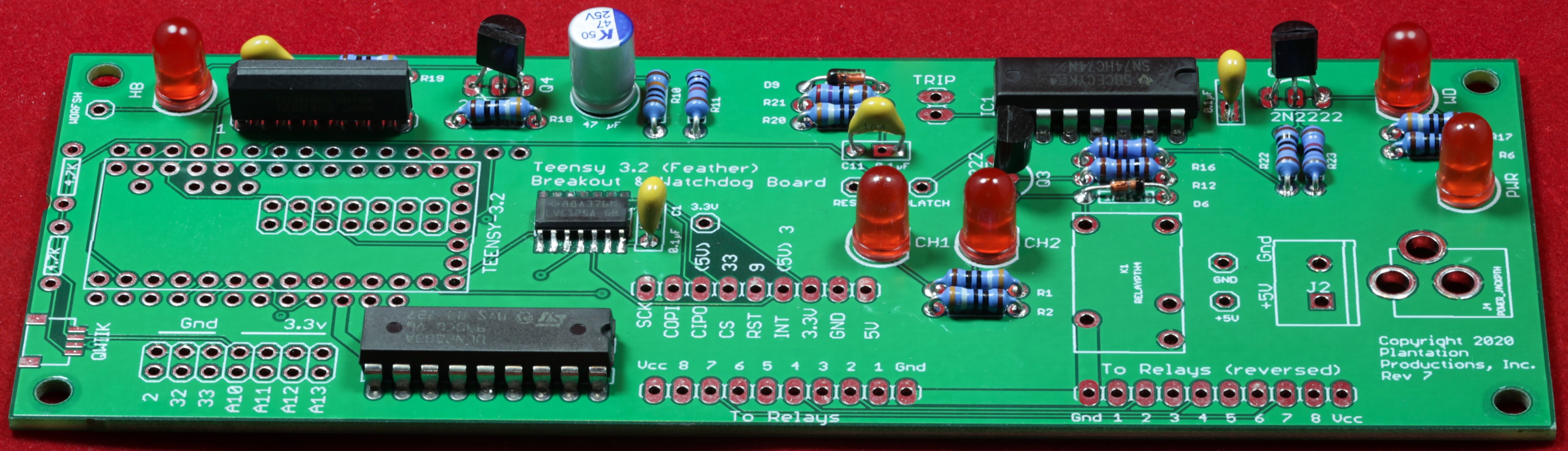
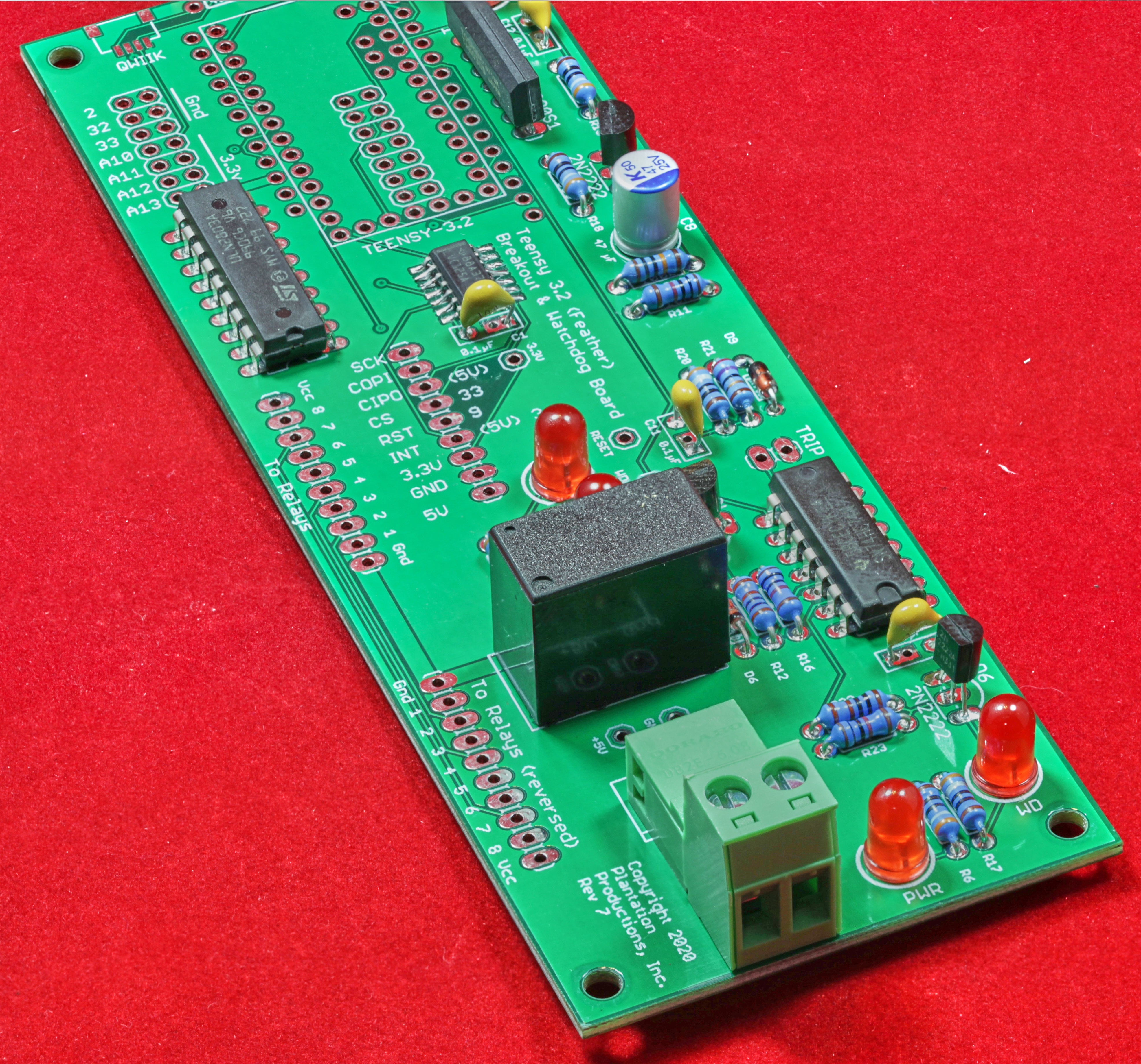
Watchdog and Breakout board for Teensy 3.2
The Ethernet Watchdog Board (EWB) was created to provide a watchdog timer service for two computers controlling a TRIGA nuclear reactor. The specific TRIGA reactor (installed at Idaho National Laboratories) is controlled by two PCs -- one running Windows (as a display terminal) and one running Suse Linux (this one actually controls the reactor). Previous to the use of the EWB, the TRIGA console used two RS-232-based watchdog timer to verify that these two PCs were running (and refreshing the watchdog timer on a regular basis). As it turns out, the RS-232-based watchdog timer scheme was not entirely reliable and the system generated spurious watchdog timeouts on a (very) infrequent basis; if the reactor was operating when this timeout occurred, it would SCRAM the reactor (which causes the generation of lots of paperwork and the regulating agency demands an explanation for the SCRAM). INL wanted a second watchdog added, based on a different technology (Ethernet, rather the RS-232) to run in parallel with the RS-232 watchdogs with a "2-of-2" logic (both watchdogs have to timeout before SCRAMming the reactor). The EWB provides this functionality.
The EWB supports two separate watchdog channels and controls four independent relays for each channel (all four relays associated with a channel are turned on/off simultaneously when a watchdog trip occurs/does not occur). At INL, three of the relays are used for
- The SCRAM circuity,
- A digital input to the Linux computer system
- A lamp control on the console
The INL console does not use the fourth relay on each channel.
The EWB connects to an Ethernet interface (I typically use the Adafruit Ethernet Featherwing, though the EWB should work with any WS5500 compatible SPI-based Ethernet device) to listen on two ports at IP Address 192.168.2.19. Obviously, this IP address is easy to change in the software. Any character arriving on socket port 20560 refreshes the first watchdog timer channel, any character arriving on port 20561 refreshes the second watchdog timer channel.
By default, both channels assume a seven-second timeout period (again, this is easy to change in the software, though the EWB may act erratically if you specify less than two seconds as other activities could result in a 2-second delay).
Because maintaining the two watchdog channels is accomplished using software on the EWB, this presents a problem: the whole purpose of the EWB is to verify that software (running on the TRIGA console computers) is periodically reporting that they are running to the EWB (which is watching those two computers). However, "who's watching the watcher?" is a good question to ask; that is, what's to prevent the EWB firmware from hanging up and failing to trigger the watchdog timeouts should the console computers stop operating? This situation is handled by a hardware watchdog timer on the EWB itself. The hardware timer (based on the TA8030S watchdog IC) times out after approximately 4.7 seconds. Should the EWB firmware fail to refresh the hardware watchdog timer in this time period, the hardware watchdog will automatically open the relays for the two channels, signalling a watchdog event.
The EWB operates in a fail-safe manner when using the "normally open" terminals on the relays. While the EWB is operating normally and there is no watchdog timeout event, the EWB applies power to the relay coils so that the normally open contacts are closed. When a watchdog timeout event occurs, power is removed from the coils and the relay opens up the normally open contacts. Note that when power is not applied (or power is lost) to the EWB, the relay's normally open contacts are in the open (fail-safe) position. Obviously, a firmware or hardware failure could cause the relays to be stuck in the closed position, even in the event of a watchdog timeout event, but that is a separate issue (for what it's worth, firmware failure is mitigated through review and testing, a hardware failure, such as a stuck relay, can be mitigated by wiring two relays in series, to open the contact if either relay is open).
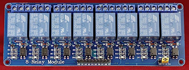
The EWB, itself, only contains a single relay (used by the hardware watchdog timer). The eight actual relays for the watchdog trip are provided by a COTS (commercial off-the-shelf) 8-channel 5v relay board. The particular board I use is a JBtek 8 Channel DC that operates off 5v and has optically-isolated inputs. Several different manufacturers offer identical (as in the same PCB) or very similar devices (e.g., JBTek, SainSmart, SunFounder, ELEGOO).
High-resolution image shot with a Canon EOS 5D MII
The K1 through K4 relays (the leftmost four relays in this image) correspond to channel 1 and K5 through K8 (the rightmost four relays) correspond to channel 2. This board also has 8 LEDs that illuminate while the corresponding relay is energized (these are SMT LEDs, labelled "IN1" through "IN8" on the PCB, the bottom-most of the 4 SMT components below each relay).
Note: You can wire the relay board to one of the correspdonding headers on the EWB. However, as of EWB Rev 7 the EWB PCB was laid out so you can stack the two boards together (the EWB and the relay board) and solder them directly together. This connection requires unsoldering the 10 header pins on the relay board, soldering a new 1x10 header with the pins facing downward rather than upward, and then sandwiching the two boards and soldering them together. This is the preferable approach as the header pins carry much more current than ribbon cable conductors and the Vcc/Gnd pins do require a bit of current.
There is a 1x10 header that provides power and control to the relays. The EWB contains a pair of electrically-compatible connectors; you use a ribbon cable (or other wiring) to connect the 10 pins on the EWB to the corresponding pins on the 8-channel relay board.
Note: The EWB hardware and software are covered under the Creative Commons Attribution 4.0 International license.
Here is the "normal person"-readable version of that license.
Here is the version for lawyers.
For more information on Creative Commons, visit their website.
For the purposes of attribution,
Copyright 2019
Plantation Productions, Inc.
Randall Hyde
Note: disclaimer of warranty appears in the legal version of the license.
Table of Contents
Overview
The Ethernet Watchdog Board is a watchdog and breakout board for the Teensy 3.2 from PJRC. It provides the following features:
- Open Hardware design based on Creative Commons 4.0 license
- Single 5V power supply input connector (screw terminals or 5.1mm barrel jack).
- LED indicates when power is applied.
- Adafruit-compatible Feather bus (compatible with software written for the feather adapter for the Teensy 3.2).
- Eight digital output lines are routed through a ULN2308 darlington array (high-current, 500ma/pin); these normally drive a set of relays for the watchdog functionality, but can be repurposed, if desired.
- Hardware watchdog timer actuates a relay after 4.7-second timeout without a refresh operation (timeout period can be changed by swapping out a different resistor).
- An LED indicates current watchdog timeout state.
- Watchdog state (relay) is available on a two-pin header (5v logic compatible signal).
- Three spare digital I/O pins and four spare analog input pins (three of which are also reprogrammable as digital inputs) are brought out on a header.
- SPI bus and several control signals (digital pins 3, 9, and 10) are brought out on a header for connection to a W5500 SPI-based Ethernet interface.
- An LED indicates when the watchdog timer is being refreshed.
- Schematic and board layout are available in Eagle format.
- DIN rail brackets are available in .STL format for 3D-printing.
Bill of Materials
Bill of Materials (BOM) for the EWB:
- (1) Teensy 3.2 CPU module
- (2) 2x7 SMT male header
- (2) 2x5 pin male header
- (2) 2x14 pin male header
- (2) 1x10 pin male header
- (1) 1x9 pin male header
- (1) 2x7 pin male header
- (1) 1x2 pin male header
- (1) 2-pin 5mm center screw terminal (preferably one that is removeable) or a 5.1mm barrel jack power socket.
- (3) 2N2222 NPN transistor
- (5) 5mm red LED
- (2) 100 kΩ resistor
- (2) 4.7 kΩ resistor
- (3) 10 kΩ resistor
- (2) 1 kΩ resistor
- (6) 390 Ω resistor
- (1) 27 Ω resistor
- (1) 47 µF capacitor
- (3) 0.1 µF capacitor
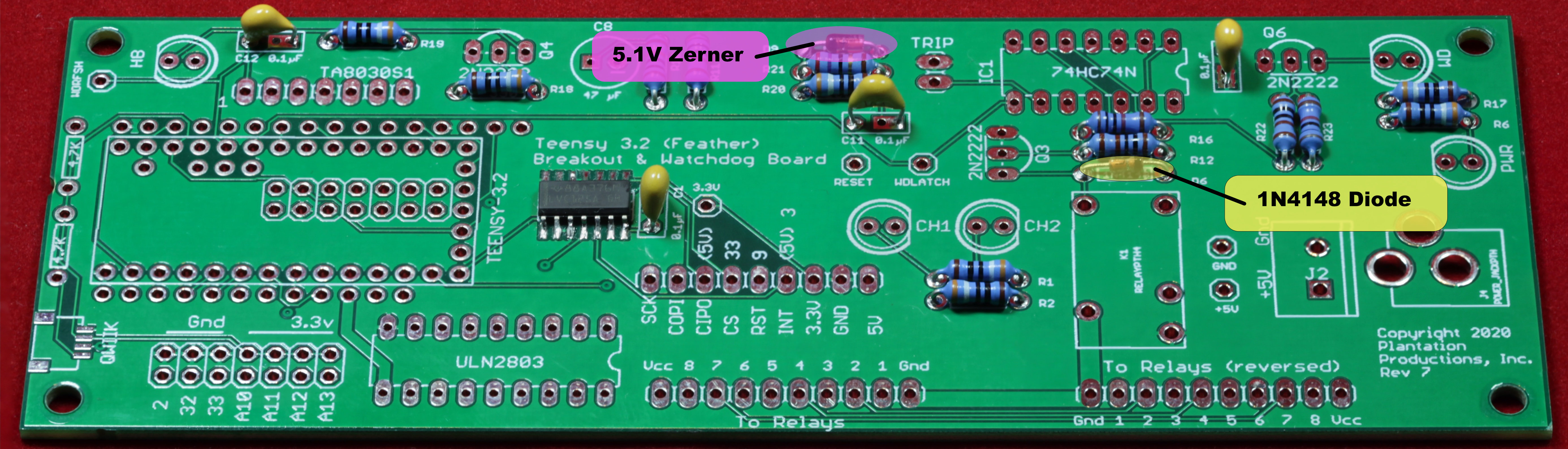
- (1) 1N4148 diode
- (1) 1N4728A zener diode (4.5 to 5.1V is acceptable)
- (1) ULN2308 Darlington transistor array
- (1) Toshiba TA8030S watchdog timer
- (1) JZC-11F-05VDC-1Z relay (Sparkfun)
- (1) 74HC74 flip-flop
- (1) 74LVC125 quad buffer
- (3-4) 1x40 female headers (some are optional)
- Optional: Qwiic SMT connector
- Optional: 14-pin DIP socket
- Optional: 18-pin DIP socket
- Optional: (6) test pins
- Optional: EWB 3D printed assembly module.
I typically use 1% resistors, though only the 100kΩ resistor used for the RC timing circuit is critical (depending on the variance you want to allow on the hardware watchdog timer).
Note: If you only want a few EWB PCBs, contact Plantation Productions (randy@plantation-productions.com) to see if there are any in stock. Bare boards are $25 each plus shipping; fully assembled and tested boards are $399. If you need more than a couple PCBs and you're not in a huge hurry, it costs about $50 (plus about 4-6 weeks) to have a set of 10 manufactured and shipped to you from China. I use Seeed Studio Fusion PCD service (https://www.seeedstudio.com/fusion.html).
EWB Files
The EWB PCBs are two-layer boards. Here are the Gerber files for them (provide these files to Seeed Studio or your personal PCB manufacturer).
If you want to modify or enhance the DAQ_IF design, or re-layout the PCB using Eagle, here are the Eagle files:
EWB Eagle files (Schematic and board layout)
If you simply want to view the schematic on-line, you'll find that here:
The "stand" for mounting the 8-channel relay board and EWB were created using AutoDesk's Fusion 360 (to produce STL files) and I personally print the results on a Lulzbot Taz6 3D printer using PLA filament (ABS is not recommended for this job, it warps and shrinks and the tolerances are off). The STL files can be found here:
The firmware for the EWB, along with several test programs, can be found here:
The system documentation for this project includes the following documents (all follow IEEE guidelines):
- SyRS: System Requirements
- SRS: Software Requirements Specification
- SDD: Software Design Description
- STC: Software Test Cases
- STP: Software Test Procedures
- SR: Software Review checklist
- HRS: Hardware requirements specification
- HDD: Hardware Design Description
- HTC: Hardware Test Cases
- HTP: Hardware Test Procedures
- HI: Hardware Inspection checklist
- RTM: Reverse/requirements traceability matrix
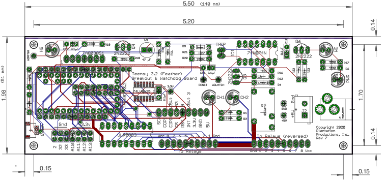
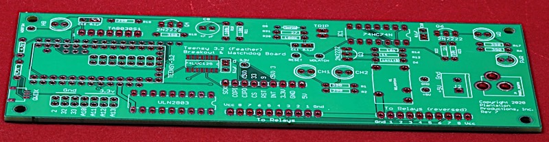
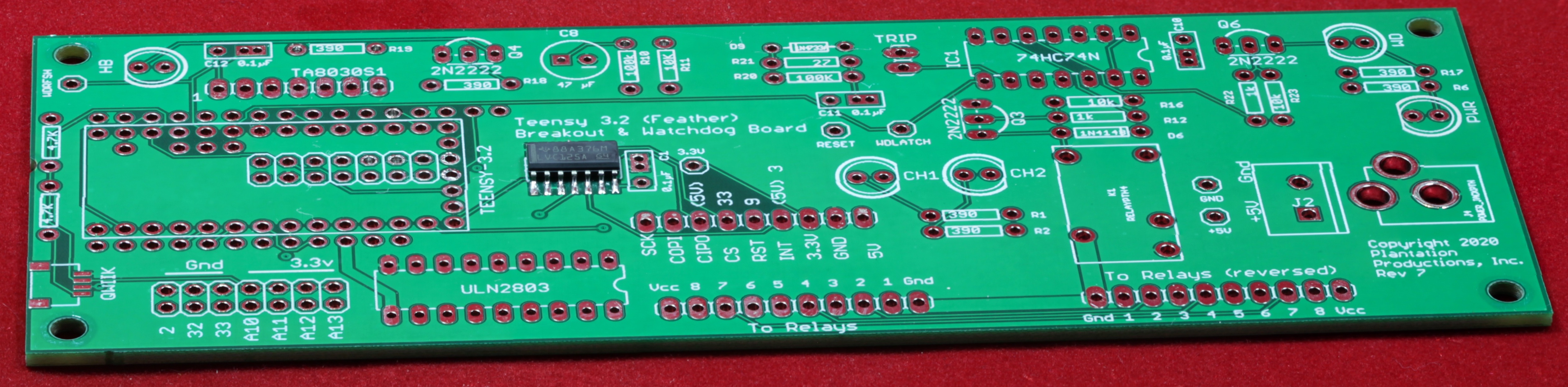
EWB Board Layout
EWB Eagle Files
The EWB Eagle PCB files contain two sets of files: EthernetWD.sch/EthernetWD.brd and EthernetWD.MT.sch/EthernetWD.MT.brd. The *.MT.* files (MT="Manual Traces") contain some manually inserted traces that handle important signals requiring special layouts (specifically, the high-current traces from the watchdog relay to the three-pin connector). If you want to make changes to the board layout, make them to the *.MT.* files; then copy the EthernetWD.MT.sch and EthernetWD.MT.brd files to the EthernetWD.sch and EthernetWD.brd files (respectively) and run the auto-router on them. When running the autorouter, be sure to load the EthernetWD.ctl file that applies higher costs to the inner layers (which should be power and ground only) and a few other routing rules.
EWB Revisions History
Rev 1:
Original Design
Rev 2:
Changed silkscreen layers for certain text.
Reversed Polarity of barrel jack.
Moved power terminal (2-pin) behind barrel jack.
Unmerged IN7 & IN8 signals.
Removed Elecfreaks interface.
Added separate Ethernet reset line.
Added Auxilliary I/O header.
Added test points.
Reversed pins on ULN2308 to improve PCB layout.
Added second relay connector with reversed pins.
Added TRIP header (on-board WD trip signal).
Added ground traces between relay and relay connectors on all layers of the PCB.
Rev 3:
Moved Teensy, power connectors, power LED, and HB LED to allow a USB cable to connect to the Teensy.
Rearranged headers to make them easier to connect to the Ethernet and relay boards.
Eliminated product-specified Ethernet connection and added an Adafruit Feather interface to allow installation of generic devices (e.g., Adafruit Ethernet FeatherWing).
Rev 4:
Corrected bad Feather layout.
Reversed pins on auxiliary connector on bottom of Teensy.
Added CH1/CH2 LEDs.
Rev 5:
Minor changes to signal names on schematic (to match hardware design description).
Moved some components away from the PCB edge.
Rev 6:
Swapped pins on power connector.
Rev 7:
Moved the relay connectors to line up with the connections
on the relay board. Rotated feather connectors.
Moved several parts around.
Switched board to four layers.
Removed 1000 uF capacitor.
Changed LED resistors to 390 ohms. Put buffers on external ETH pins.
Added Qwiic connector and I2C pullup resistors.
EWB Functionality
The EWB provides the following functionality:
- Support for up to eight relays via the high-current output port (ULN2803 darlington). Nominally used to control two watchdog channels with 3-4 relays per channel. Could easily be reconfigured to support 2, 3, 4, 5, 6, 7, or 8 separate channels (depending on the number of relays needed for each channel). Can also be used to control other moderate power (up to 150 mA) devices.
- Adafruit Feather compatible bus - Electrically identical to the Teensy 3.2 Feather adapter from Adafruit.
- 4.7 second watchdog timer with SPDT NC/COM/NO (normally closed/common/normally open) relay. Useful in safety critical systems to detect when the software has frozen. Hardware can automatically reset itself or place the system in a fail-safe mode when a watchdog timeout occurs. Timeout is nominally 4.7 seconds but you can easily change it by substituting a different resistor value.
- SPI interface pins for generic SPI-controlled W5500-based Ethernet interfaces.
- 2x14 header breakout for otherwise unused pins on the Teensy 3.2
In addition to the above, the EWB features LEDs indicating the following:
- Power applied
- Hardware watchdog timeout
- Heartbeat/watchdog refresh/general purpose LED output
- Channel 1/Channel 2 WD timeout.
The EWB also includes numerous test pins to aid in testing and maintenance of the board.
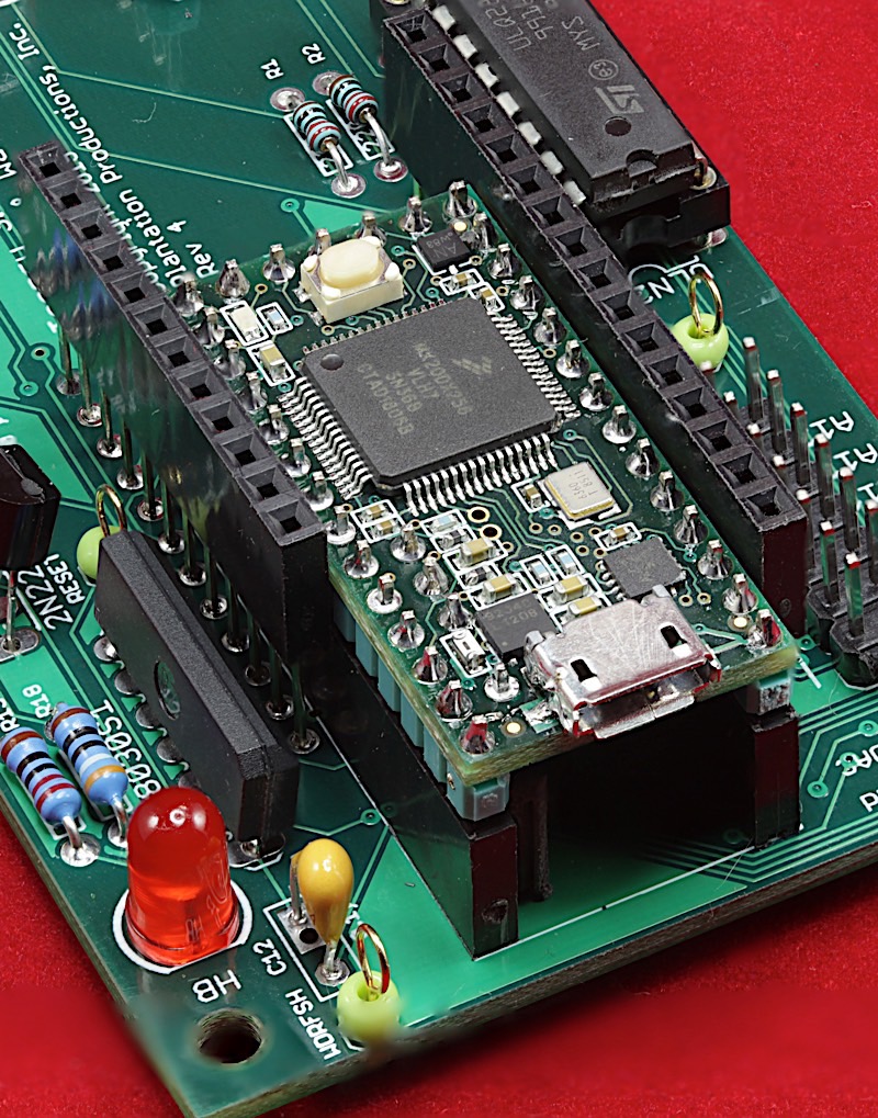
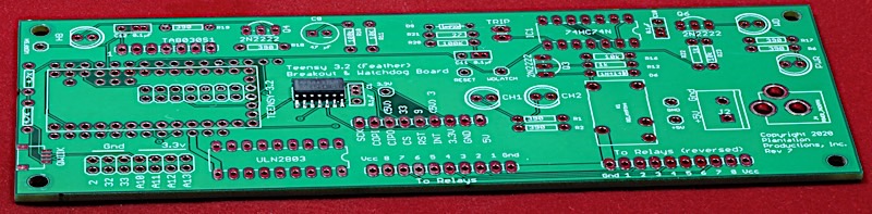
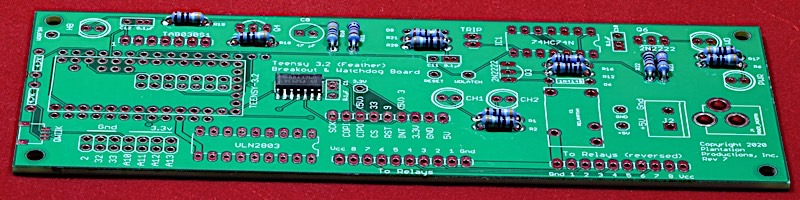
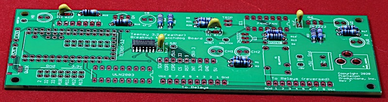
Components on the EWB Board
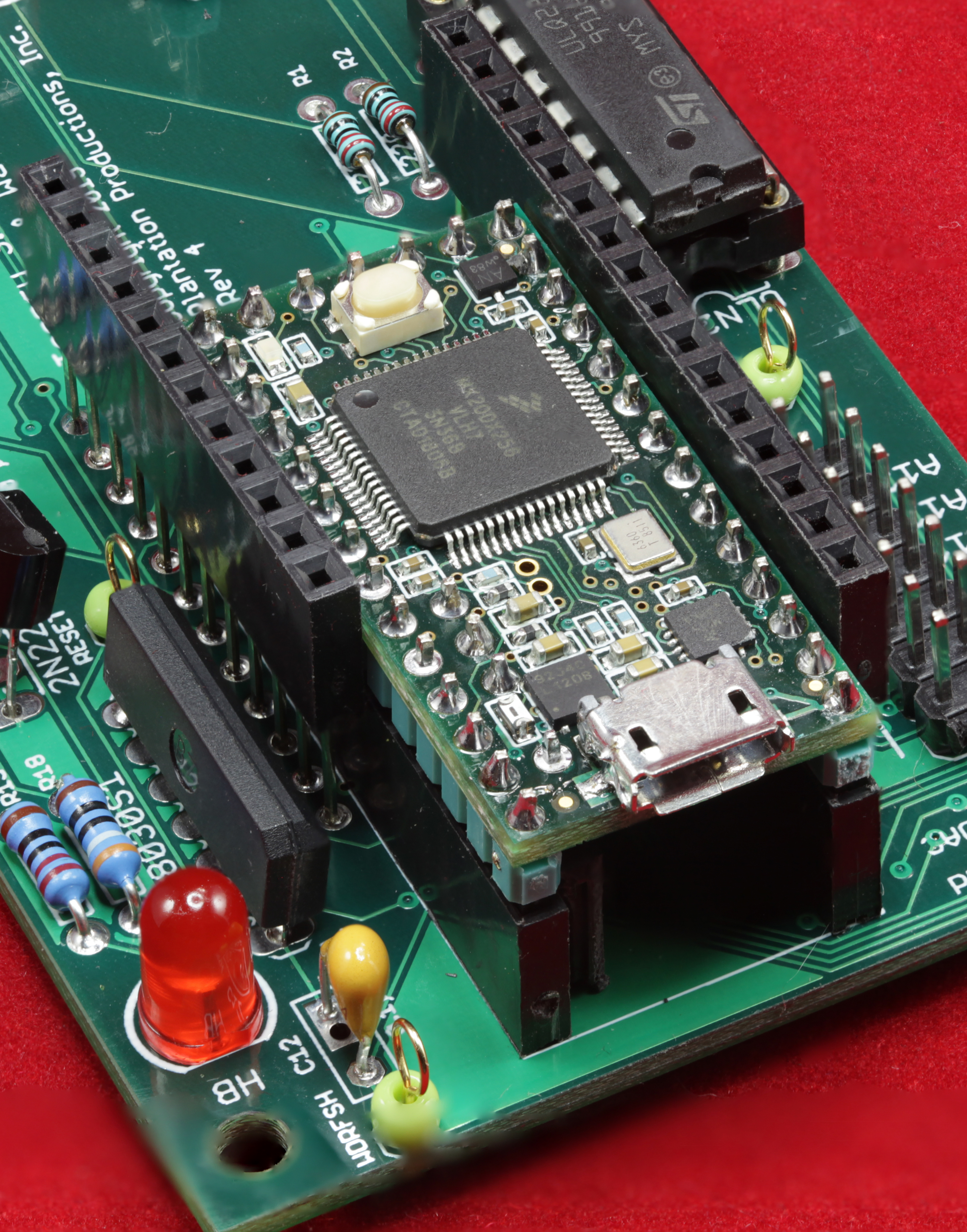
EWB and Feather bus
High-resolution image shot with a Canon EOS 5D MII
The EWB brings out a set of two headers that are physically and electrically compatible with the Adafruit Feather bus as implemented on Adafruit's Teensy 3.2 Feather adapter.
The Adafruit Feather bus headers (JP3 and JP4) straddle the Teensy 3.2 CPU board on the EWB:
The Feather bus is a 3.3V I/O bus support digital and analog I/O as well as SPI and I2C periperals (also 3.3V). The pinouts for the Feather bus are as follows (Note that pin 1 is the pin on both connectors farthest from the Teensy):
| Pin | Function |
|---|---|
| 1 | Gnd |
| 2 | TX1 |
| 3 | RX1 |
| 4 | MISO0 |
| 5 | MOSI0 |
| 6 | SCK0 |
| 7 | A6 (analog input 0-3.3V) |
| 8 | A0 (analog input 0-3.3V) |
| 9 | A2 (analog input 0-3.3V) |
| 10 | A3 (analog input 0-3.3V) |
| 11 | A1 (analog input 0-3.3V) |
| 12 | DAC0 |
| 13 | Gnd |
| 14 | ARef |
| 15 | 3.3v supply (max 250mA) |
| 16 | Program |
| Pin | Function |
|---|---|
| 1 | VBat |
| 2 | N/C |
| 3 | Vcc (3.3v) |
| 4 | Digital I/O pin 5 (3.3v only) |
| 5 | Digital I/O pin 6 (3.3v only) |
| 6 | Digital I/O pin 9 (3.3v only) |
| 7 | Digital I/O pin 10 (3.3v only) |
| 8 | Digital I/O pin 4 (3.3v only) |
| 9 | Digital I/O pin 3 (3.3v only) |
| 10 | Digital I/O pin 8 (3.3v only) |
| 11 | SCL0 (3.3v, with 10K pullup to +3.3v) |
| 12 | SDA0 (3.3v, with 10K pullup to +3.3v) |
Adafruit sells a variety of "Feather Wings", which are little I/O modules, that plug into a Feather bus connector. Most of these are compatible with the Feather bus implementation on the EWB, though the Ethernet Featherwing is the standard Featherwing when using the EWB as an Ethernet-based watchdog timer; of course, if you're using the EWB for a different purpose, any Featherwing that does the job you need is suitable. Examples of useful Featherwings include:
- Adafruit Feather Huzzah w/ESP7266 WiFi
- Adafruit Featherwing proto boards
- Adalogger Featherwing
- Featherwing OLED
- Adafruit Ultimate GPS Featherwing
- Adafruit Power Relay Featherwing
- Adafruit DS3231 Precision RTC Featherwing
- Adafruit TFT Featherwing (2.4" touchscreen)
- Adafruit DC Motor+Stepper Featherwing
- Adafruit Featherwing doubler
- Adafruit Neopixel Featherwing
- Adafruit Non-latching Mini Relay Featherwing
- Adafruit LoRa Radio Featherwing
- Adafruit Ethernet Featherwing
- Adafruit Terminal Block Featherwing
- Adafruit 8-channel PWM/Servo Featherwing
- Adafruit 8x16 LED Matrix Featherwing
- Adafruit 7-segment display Featherwing
- Adafruit Musicmaker Featherwing
- Adafruit CharliePlex 15x7 LED matrix display Featherwing
- Adafruit Quad Alphanumeric Featherwing
- More stuff appearing all the time
For more information, visit the Adafruit Feather web page: https://www.adafruit.com/category/943.
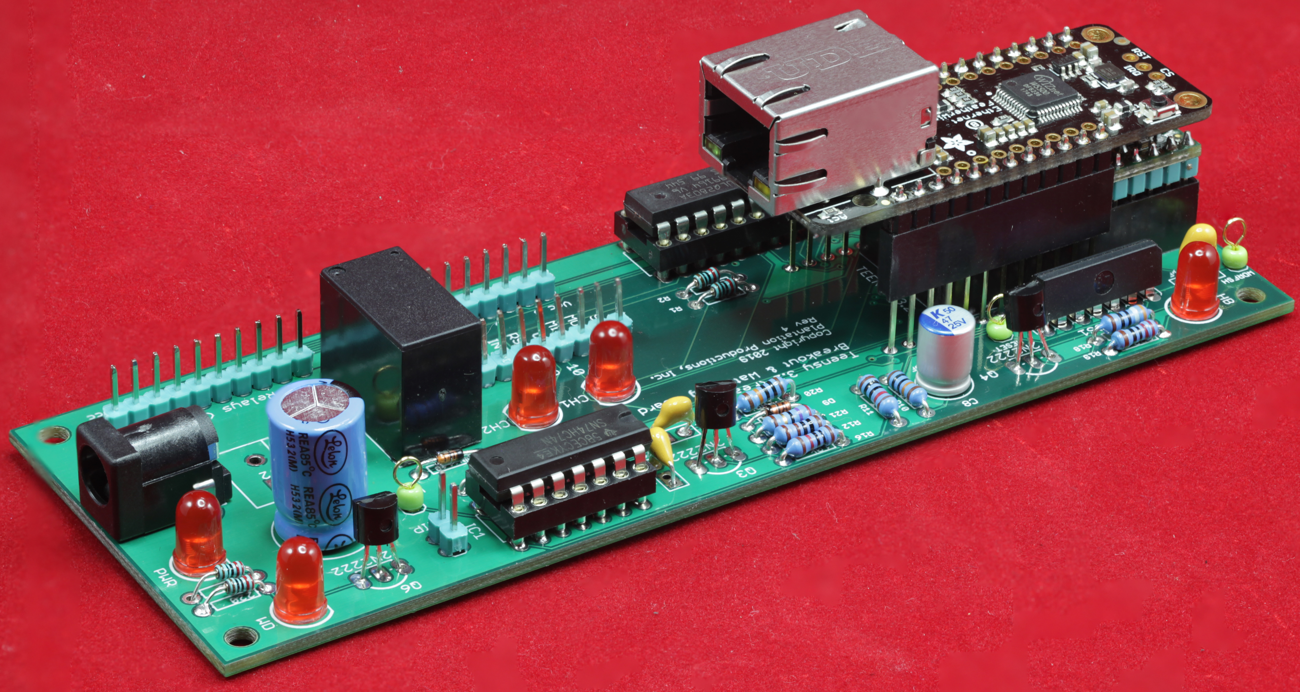
EWB with Adafruit Ethernet Featherwing installed:
High-resolution image shot with a Canon EOS 5D MII
Before you start emailing me with your concerns, yes, the Ethernet Featherwing is installed "backwards." I reversed the Feather headers from what you would normally expect (with the Ethernet RJ-45 jack pointing the other way) to ease board layout considerations. This made it possible to create a 2-layer PCB rather than having to go to a (5x more expensive) 4-layer board. The small inconvenience of having to insert the Ethernet cable across the body of the EWB was worth the ability to layout the board with only two layers.
Watchdog Control on the EWB
The EWB has a hardware watchdog timer on board. Note that this watchdog timer is different from the one built into the CPU on the Teensy 3.2 board; the Teensy's watchdog timer (when appropriately programmed) will reset the CPU if the watchdog timer times out. The watchdog timer on the EWB actuates a relay if the watchdog timer expires. The ground return from the relay board (the Gnd pin on the "To Relays" connectors) is interrupted if the hardware watchdog times out. This cuts power to the relay board and puts it in a fail-safe condition (all relays open). During normal operation, the Teensy refreshes the hardware watchdog timer every second or so (which also blinks the HB/Heart Beat LED so you can see that the refresh operation is taking place). Unless the CPU hangs up, this will continually refresh the hardware watchdog timer and prevent a timeout condition.
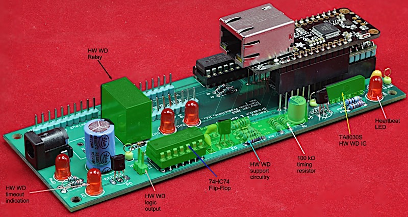
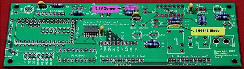
The Toshiba TAB030S watchdog timer IC determines its timeout period via an RC (resistor-capacitor) circuit. R10 on the EWB (nominally 100 kΩ) and the 47 µF capacitor next two determine the timeout period (100,000 * 0.000047 is 4.7 seconds). If you want to change the timeout period, the best solution is to replace R10 with a different resistor value.
The TAB030S watchdog IC expects a pulse on its watchdog refresh pin at least once every watchdog timout period (nominally 4.7 seconds). More frequent is okay, but if the refresh pulse does not arrive in (approximately) 4.7 seconds, the TAB030S will send a pulse to the watchdog latching circuit. The watchdog latching circuit consists of a 74HC74 flip-flop and the pulse from the TAB030S IC will toggle the "set" input on the flip-flop. This, in turn, drives the watchdog LED (illuminating it if there is a latched watchdog time) and actuating the watchdog relay. To prevent the watchdog state, the software running on the EWB must pulse the watchdog refresh pin (digital output pin 22 on the Teensy 3.2) by writing a zero to the pin and then writing a one to the pin.
#define eth_reset	(9)
#define wd_rfsh     (22)
#define wd_latch    (21)
#define Reset       (23)

void setup()
{
		.
        .
        .
    pinMode( wd_rfsh, OUTPUT );
    pinMode( Reset, OUTPUT );
    	.
        .
        .
}


// Must send a positive pulse to the TA8030s
// to refresh the watchdog timer:

void watchdogRefresh( void )
{
    digitalWrite( wd_rfsh, 1 );
    delay( 1 );
    digitalWrite( wd_rfsh, 0 );
}
Should the watchdog timer expire, you must explicitly reset the watchdog timer. Pulsing the watchdog refresh pin will not reset the timer. Instead, you must pull the reset pin (Teensy 3.2 digital output pin 9) low for at least 350 msec.
// Must send a negative-going pulse to the DS1834
// chip to cause a reset. The pulse must be at least
// 350 msec wide.

void toggleReset( void )
{
        digitalWrite( Reset, 1 );
        delay( 500 );
        digitalWrite( Reset, 0 );
        delay( 500 );
        digitalWrite( Reset, 1 );
}
If you would like to read the state of the watchdog latch, program pin 21 (wd_latch) as an input pin. This returns the current state of the watchdog latch.
SPI I/O on the EWB
The EWB supports two connections to the Teensy 3.2 SPI bus: via the Feather bus connections and via the 1x9 SPI bus connector. The EWB has been tested with the Adafruit Ethernet Featherwing and this is the assumed Ethernet interface for the EWB. However, it is also possible to connect any SPI W5500 Ethernet interface board to the EWB using the 1x9 pin header on the EWB. These pins have the following signals (viewed from left to right, with the leftmost pin being closest to the Teensy 3.2):
- SCK: SPI clock
- MOSI: SPI output signal
- MISO: SPI input signal
- CS: Digital output pin 10 on the Teensy 3.2 (standard SPI chip select signal)
- RST: Resets the interface (digital pin 9 on the Teensy 3.2); note that the standard Arduino Ethernet module does not use this pin, but if you pulse it, it will most certainly reset the W5500 IC.
- INT: Interrupt (digital pin 3 on the Teensy 3.2); useful for interrupt-driven systems; note that the Arduino Ethernet module does not use this pin.
- 3.3V: 3.3V output from the Teensy 3.2. You get about 100-150 mA on this pin. Can be used to power the SPI Ethernet interface if it doesn't draw too much power
- Gnd: Ground signal
- 5V: Power from the EWB power connector.
If you are using some SPI W5500-based Ethernet interface other than the Adafruit Ethernet Featherwing, you will need to connect your device to the EWB through these pins. However, that work is beyond the scope of this document and Plantation Productions, Inc., makes no warranties concerning the suitability of any particular Ethernet interface for use with the EWB.
Relay Output on the EWB
The EWB supports two 1x10 headers that transmit information to an 8-channel relay board. The difference between the two headers is that one header has the pins reversed. This makes it eaiser to connect to the relay board, without twisting the ribbon cable connecting the EWB to the relay board, if the orientation requires reversed pins. In the Rev 7 version of the EWB, these pins are aligned such that the EWB can be mounted, back-to-back, with the relay board by unsoldering the header on the relay board and soldering a new set of header pins with the pins facing downward.
The 10 pins have the following signals (all labeled on the PCB):
- Gnd: Signal ground
- In1: signal to control relay one (active low).
- In2: signal to control relay two (active low).
- In3: signal to control relay three (active low).
- In4: signal to control relay four (active low).
- In5: signal to control relay five (active low).
- In6: signal to control relay six (active low).
- In7: signal to control relay seven (active low).
- In8: signal to control relay eight (active low).
- Vcc: +5v power supply to the relay board.
The following Teensy 3.2 pins control these outputs:
#define out7 (24) // In 8
#define out6 (25) // In 7
#define out5 (26) // In 6
#define out4 (27) // In 5
#define out3 (28) // In 4
#define out2 (29) // In 3
#define out1 (30) // In 2
#define out0 (31) // In 1
Writing a "1" to these output bits energizes (actuates) the relay. Writing a zero to these pins deactivates the relay. Note that the Teensy output pins are fed through a darlington transistor array, which effectively inverts the signal. Although the relay board inputs are actually active low, writing a '1' to the corresponding Teensy output pin is what programs a '0' on the corresponding relay input pin.
Auxiliary I/O on the EWB
The EWB contains a 2x7 header that provides seven additional signals (plus Gnd and 3.3V) that the EWB doesn't use for watchdog purposes. These pins are the following:
- digital pin 2 + Gnd
- digital pin 32 + Gnd
- digital pin 33 + Gnd
- analog pin A10 + 3.3v
- analog pin A11 + 3.3v
- analog pin A12 + 3.3v
- analog pin A13 + 3.3v
Assembling the EWB
The first step is to solder on the SMT (surface mount technology) parts. There are two SMT objects on the PCB: the 74LVC125 IC and the Qwiic connector (this connector is optional, and typically left uninstalled for Watchdog purposes). In these instructions, the 74LVC125 is install but the Qwiic connector is not. Because the 74LVC125 is a surface-mount part, care must be taken when soldering it onto the PCB. It is an SOIC-14 package; large enough that you won't need a microscope, but small enough that you'll probably want to use a magnifying glass when soldering it onto the board. Be careful not to create any solder bridges across the pins.
Next, solder the resistors onto the board:
- (1) 27 Ω resistor
- (6) 330 Ω resistor
- (2) 1 kΩ resistor
- (3) 10 kΩ resistors
- (2) 100 kΩ resistors
- (2) 4.7kΩ resistors (optional)
Note: R10 (100K) can be changed to vary the hardware WD timeout period. (47 µF * 100KΩ = 4.7 seconds). Note that you can substitute 470Ω resistors for the 390Ω resistors, as most of them are current-limiting resistors for LEDs. R20 is the only one that is not an LED resistor, and it probably won't hurt to make it 470Ω if you don't have any 330Ω resistors handy.
The 4.7kΩ resistors are pullup resistors for the I2C bus (the Qwiic connector and on the Feather bus). Generally, I2C boards (Qwiic or Feather) already have pullups so these won't be necessary in that situation. Furthermore, as a pure Watchdog board, the EWB does not use the I2C bus (so again, the 4.7kΩ resistors won't be necessary). This installation example does not install these resistors. However, if you're going to use I2C peripherals that don't supply pullup resistors, you should add these resistors during this step.
Due to the timeouts appearing in the Teensy’s (Arduino) Ethernet library, the minimum watchdog timeout period should be around 2 seconds (R10=20KΩ). You can choose a resistor value that produces a timeout less than this, but in certain circumstances the hardware watchdog timer could timeout even though the Teensy’s software has not hung up.
Technically, you could change the timeout period by swapping a different capacitor value for C8 (listed as a 50 µF capacitor, though the real-world value will be 47 µF). However, the holes on the PCB are drilled for a 47 µF capacitor and substantially larger or smaller values may not fit in the holes.
Install all three 0.1 µF bypass and filter capacitors (C10, C1, and C12).
Next, install a 1N4148 diode at D6 and a 1N4733A (5.1v Zener) diode at D9. Watch the polarity on these devices. Note that the two diodes are reversed with respect to one another (for board layout purposes; be careful that you don’t automatically install them in the same direction).
Install the (3) 2N2222 transistors and (5) LEDs. Be mindful of the polarity of these devices. Note that the shorter leg on the LEDs (-) should be closest to the flat side of the LED silkscreen image. Also, make sure you are using 2N2222 transistors, not P2N2222 transistors (technically, P2N2222 will still work, but you have to reverse the leads).
Install a two-pin header for the trip connection (logic level output).
Install a 14-pin socket for the 74HC74 flip-flop IC (optional). You can also solder the 74HC74 directory onto the circuit board, if you prefer. If you install a socket, go ahead and place the 74HC74 chip into the socket at this point.
Install an 18-pin socket for the ULN2803 Darlington array IC (optional). You can also solder the ULN2803 directly to the board (though of all the chips to die, this is probably the one so a socket is not a bad choice). If you install a socket, go ahead and install the ULN2803 in the socket at this point.
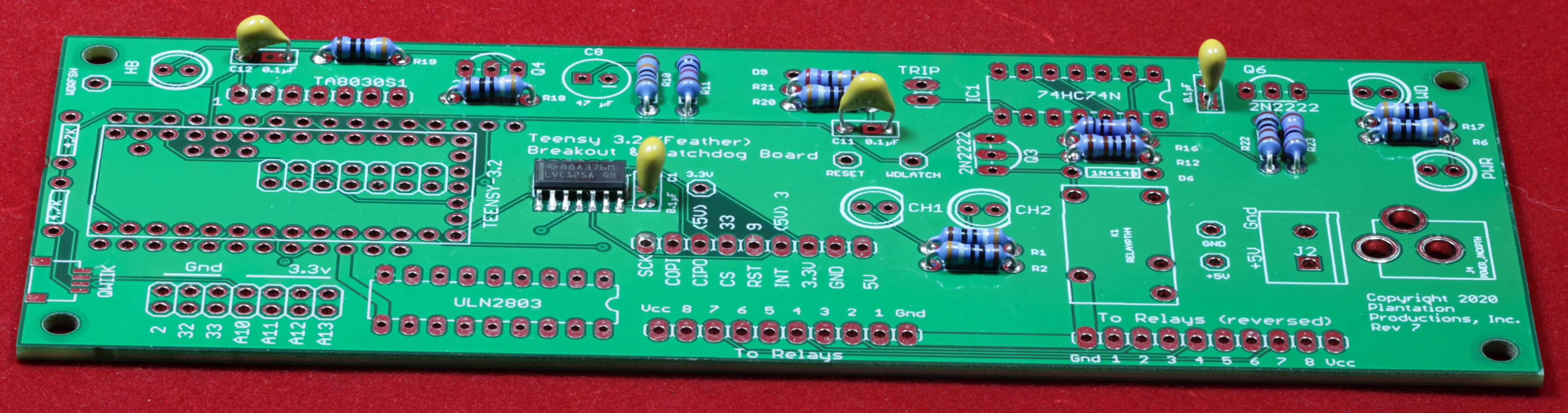
Note: As soldered-in chips are more reliable, the figures in this example construction show the chips soldered onto the board.
Install the TA8030S watchdog timer chip. Note that pin 1 of the SIP is marked with an angle cutout on the corner of the device. Make sure that pin 1 (underneath this corner) matches the hole marked by a silkscreened “1” on the PCB.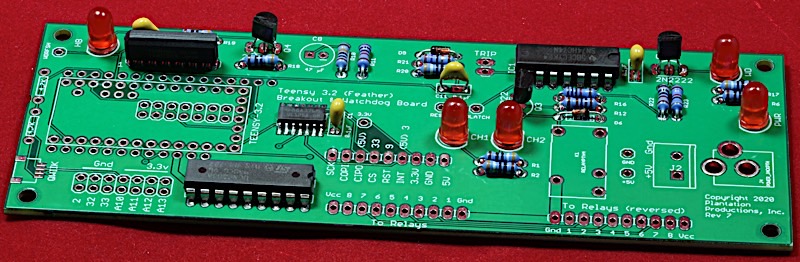
Install the 47 µF (time constant) capacitor on the PCB.
Note: although electrolytic capacitors usually have the (-) pin marked on the case, you can also determine the polarity by observing the pin length. The shorter pin is the (-) terminal. Be sure to get the polarity correct when installing these parts.
Install the power supply connector. The Ethernet Watchdog Board supports either a 5.1mm barrel jack connector (center pin positive) or a 2-pin screw terminal. In the picture, I’ve installed a (removable) 2-pin terminal. Note that you should not install both power supply connectors, pick one for your application and use that. The following two pictures show the board (at this point) with either connector installed.
Install the JZC-11F 5v relay (Sparkfun COM100 part).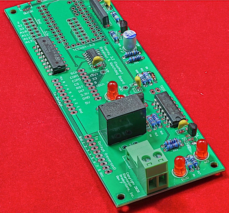
Now it is time to install the headers. Install a 1x9 header in the auxiliary Ethernet adapter connection (labeled SCK, MOSI, MISO, CS, RST, …)
(Optional) Install a 2x7 (14-pin) header in the I/O header holes on the PCB. The Ethernet Watchdog function does not use these signals. They are simply some unused digital and analog I/O pins that have been brought out from the Teensy 3.2 for possible future use. Whether you install this header is up to you.
There are two sets of 1x10 header connections just below the relay on the PCB. Both connections drive an 8-channel relay board. The difference is that one of the connections has the pins reversed. The main reason for having these two connections is ensure that the cable going to the relay board doesn’t have to twist to make the connection (if it does, use the other connector to untwist the cable).
In theory, you could populate both sets of holes with a pair of 1x10 headers. I like to use a 2x10 cable (wasting half the pins, but the cable is easier to construct with an insulation displacement cable press) so I only populate the connector I want to use (as the pins on the other connector will interfere with the 2x10 connector). If you use a 1x10 cable, this issue won’t affect you.
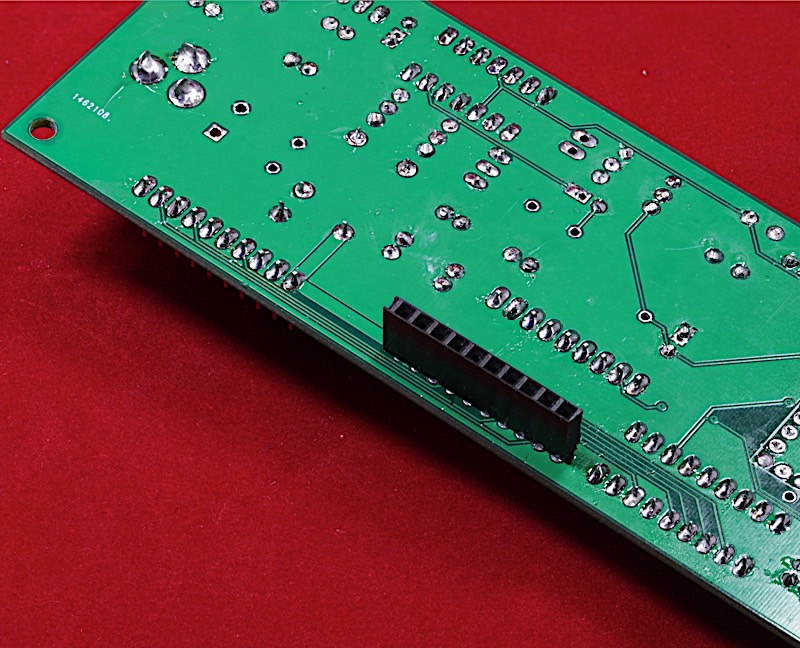
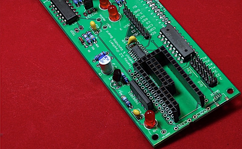
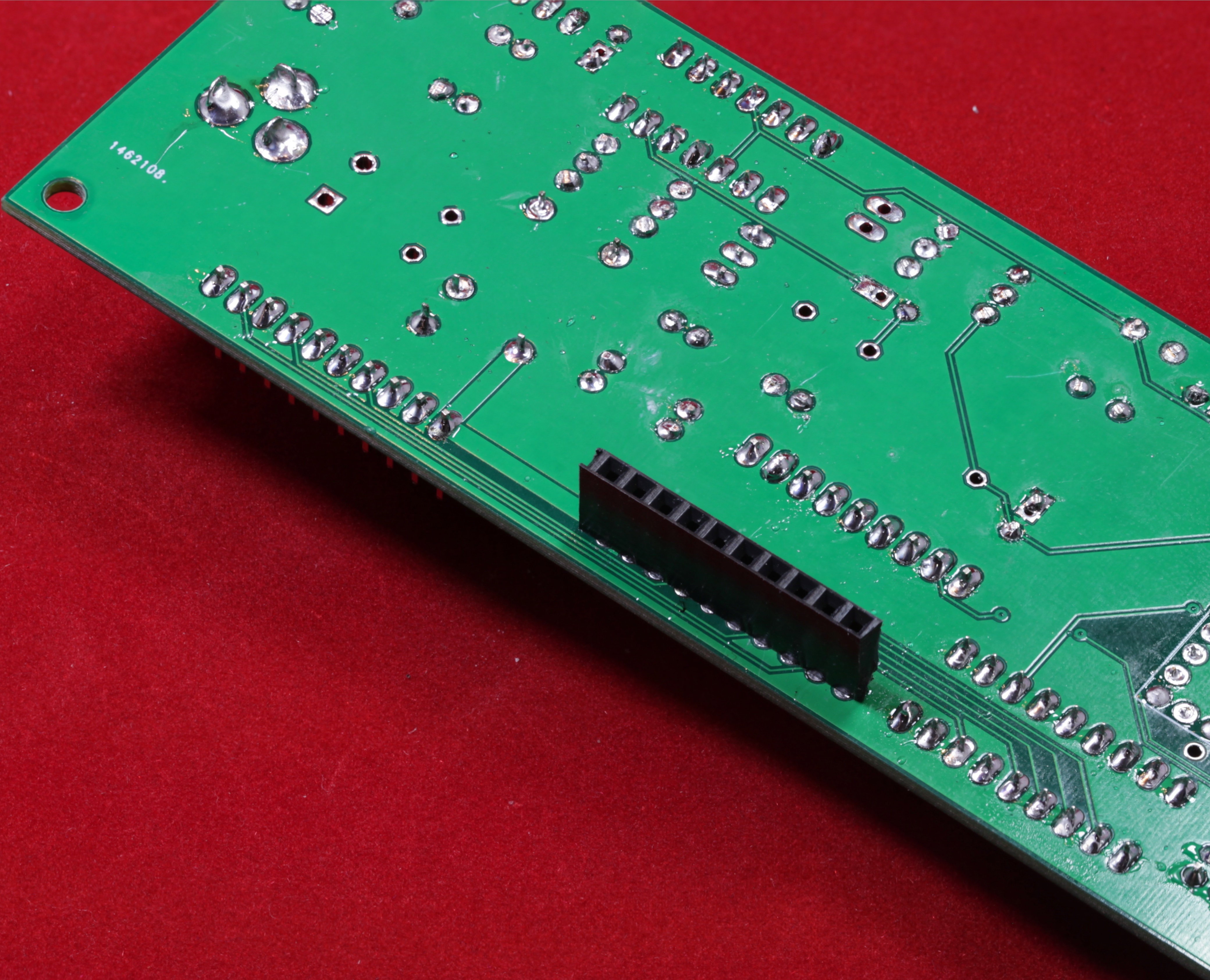
If you would prefer to wire the EWB directly to the relay board without using a ribbon cable, leave out the 1x10 header in the middle of the board (the red one in the picture below). Later, you will solder the header from the relay board directly into the back of this board through those holes.
If you would like to wire the relay board directly to the EWB but you don't want a hard connection, you can put a female 1x10 header into the middle slot as shown in the following image. Note that the female header must be soldered onto the bottom of the board, as the EWB and relay boards mount back-to-back:
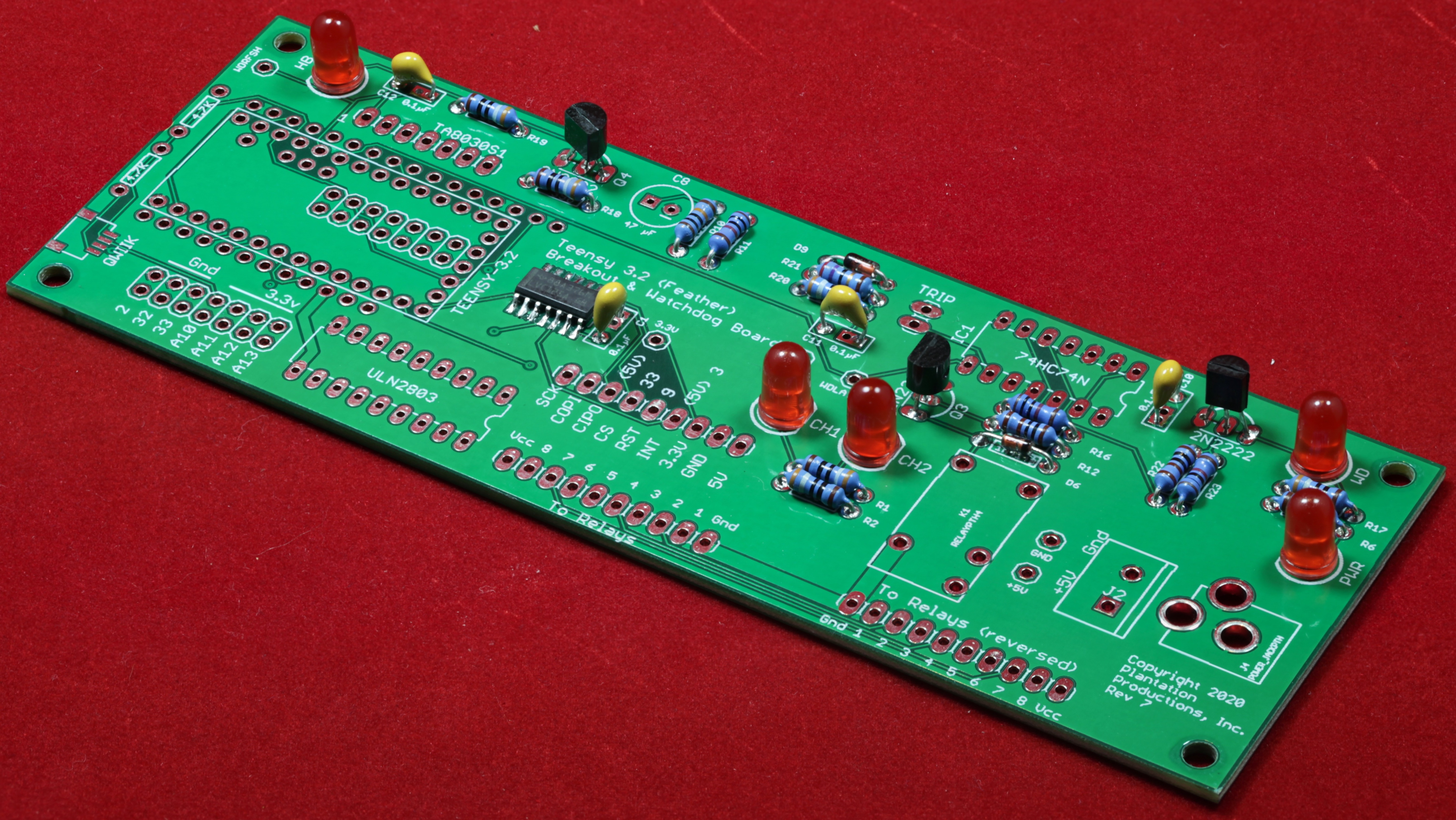
This completes the construction of everything on the Ethernet watchdog board except the Teensy 3.2 and Feather bus. Before installing the Teensy, it’s probably a good idea to do a “smoke test” on the board. Apply 5v to the board via the power connector (barrel jack or 2-pin screw terminal, whichever you installed). The Power LED should illuminate. The WD LED may or may not illuminate, and it might change state after several seconds; ignore it.
If the Power LED illuminates with no issues, good; move on to the next step. Otherwise you get to trace all your solder connections to make sure you have all the pins soldered and you don’t have a solder blob causing a short.
At this point you might want to plug your Teensy 3.2 into a (powered) USB port and verify that it comes up. If this is a Teensy 3.2 straight out of the package, it is preprogrammed with the “Blink” sketch. When you apply power, the Teensy’s LED should begin blinking. (If you have programmed the Teensy prior to this point, presumably it is known to be working; if you care to test it, you can always program the Teensy 3.2 Blink.ino program into the Teensy).
Adding Headers to the Teensy 3.2
The following section describes how to solder all the headers onto a Teensy 3.2 using a "one-off" procedure (that is, a scheme to use if you're only going to create a single EWB or other device using all the pins on the Teensy 3.2). If you're going to be creating several EWB boards, or other projects using Teensy 3.2 devices (such as any of the Plantation Productions' EtherPort boards), you should really consider creating a jig for soldering pins onto the Teensy 3.2. THIS LINK describes how to build such a jig. Using the jig is about five times faster and easier than this one-off process.
Before doing anything else, be sure to cut the VIN/VUSB trace on the bottom size of the Teensy 3.2. The Teensy 3.2 will receive power from the Ethernet Watchdog Board, not the USB connector. For proper operation (and to prevent a short), this tiny trace must be cut (See the back side of the “Welcome to Teensy 3.2” card that ships with the Teensy 3.2).
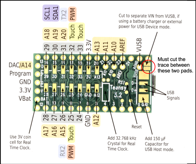
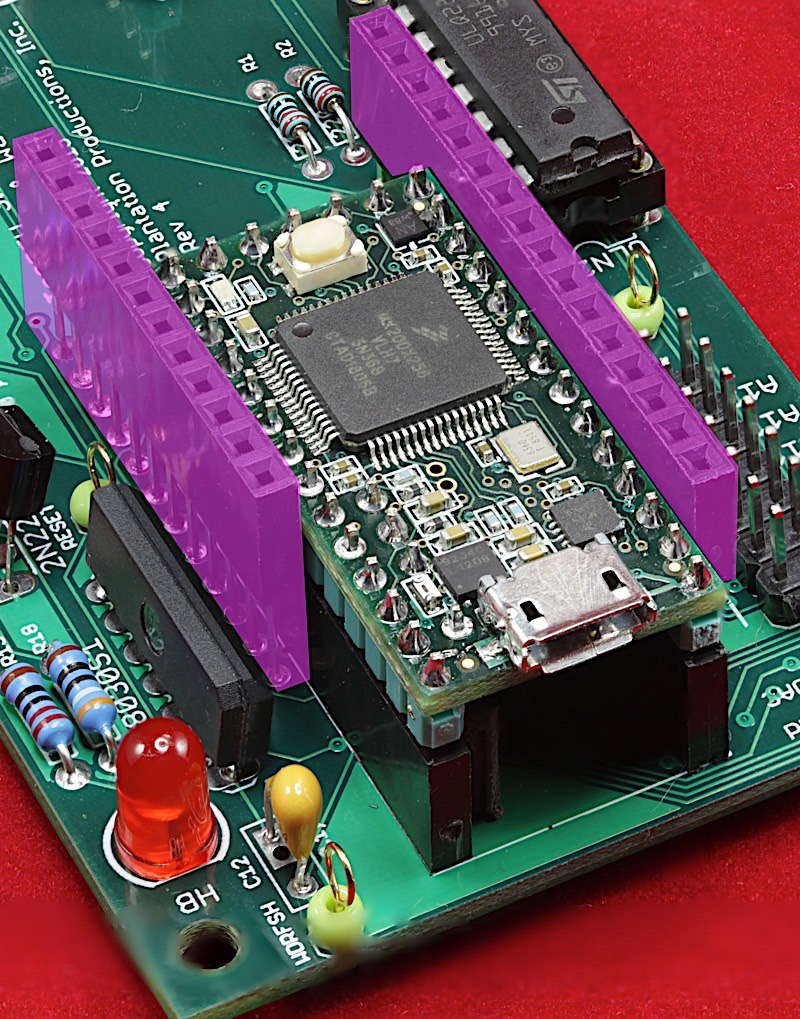
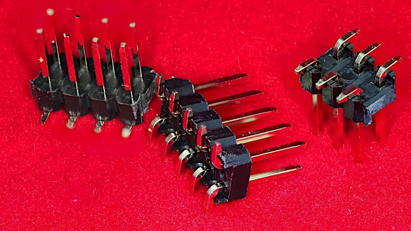
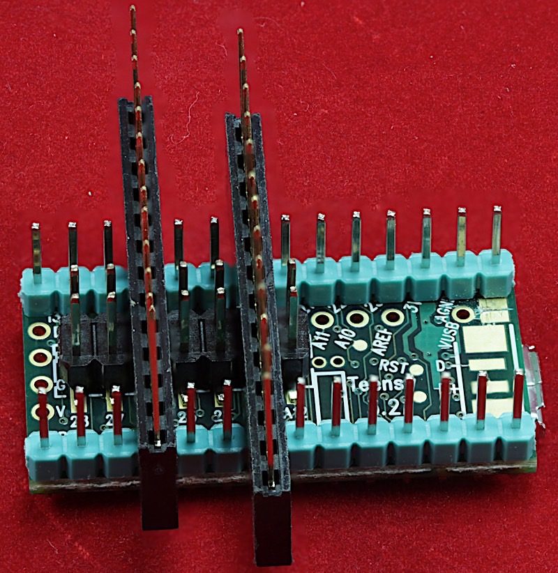
Perhaps the hardest part of building an EWB is finding the 2.54mm pitch two-row SMT/SMD male headers. The EWB requires a 2x7 SMT male header to provide access to the extra I/O pins present only on pads on the bottom of the Teensy 3.2:
There are two methods I use to solder these SMT headers onto the bottom of the Teensy 3.2: the easy (but less precise) way, and the precise way.
The easy way requires two 1x9 header strips, two 1x7 (or larger) female headers, and one 2x7 SMT header. Insert the male headers into the holes on the bottom of the Teensy (as shown in the following photo) and create a bridge across the two headers using the female headers. Be sure to keep these headers away from the end of the Teensy, so as to make the SMT pins (on D28, D29, D27, and D30) accessible for soldering:
Solder the 4-6 accessible pins onto the Teensy 3.2 board. Remove the soldering jig and finish soldering the remaining pins on the SMT connector.
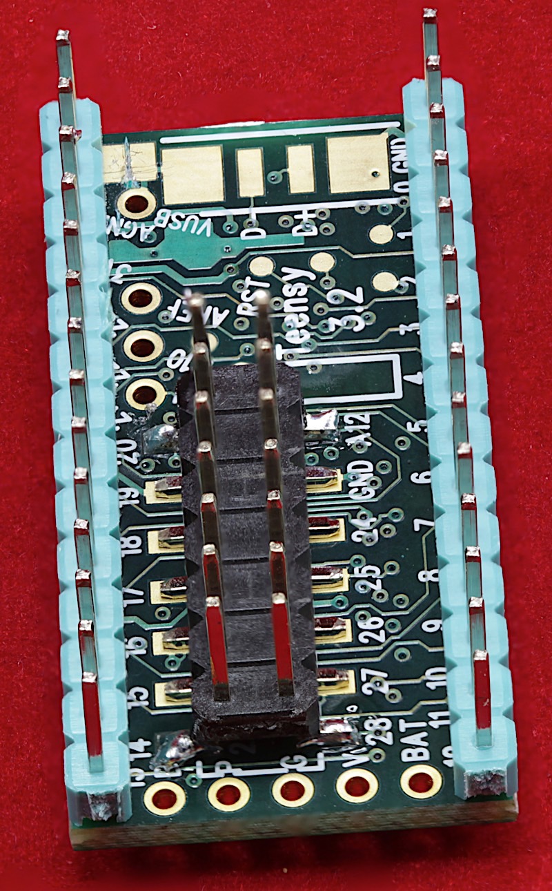
This scheme is easy because the SMT pins are relatively accessible throughout the process. However, as the soldering jig is not physically bonded (i.e., soldered) onto the Teensy 3.2, there is a bit of "play" in the mechanics, so the SMT position can be a bit loose. To achieve higher tolerances, you can use the second approach I employ. The advantage to the second approach is that you solder the outside 1x14 male headers onto the Teensy (typically using one of the solderless/plug wire prototyping boards as the soldering jig) and then build the bridge to hold the 2x7 SMT header in place. This is a bit more precise, but makes the soldering task a bit more difficult.
Begin by soldering only the outside pair of 1x14 headers:
Next, you’ll solder on the 2x7 SMD header onto the auxiliary pins on the bottom of the Teensy 3.2. To ensure that the pins will properly fit in the holes on the EWB PCB, I typically use a pair of female headers to hold the header in place while I solder down a few of the pins.
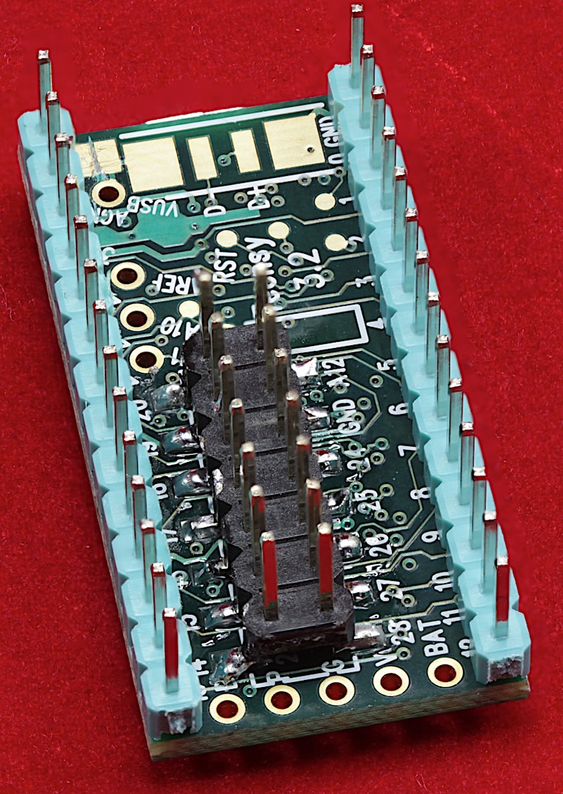
Important! Before soldering down the 2x7 header, make sure the ends of the header are carefully trimmed (especially the end that will butt up against the 1x5 header that will be placed at the end of the Teensy). If the plastic protrudes too much, it will prevent the 1x5 header (VBat, 3.3v, Gnd, Program, and A14/DAC) from going into the holes at the end of the Teensy board. It’s much easier to trim the 2x7 header before soldering it down to the Teensy (it’s still possible to trim it later, but it’s a lot more work and you have to take a lot more care when doing it after the header has already been soldered down).
Tack-solder the four corner pins of the 2x7 SMD header to the bottom of the Teensy 3.2 board. After tacking down the four corners, you can remove the female headers (assembly jig):
Carefully solder the remaining pins on the 2x7 header to the bottom of the Teensy 3.2 PCB. This will take a fine-tipped soldering iron and a bit of care.
Note: The outside row of pins really get in the way of this task, especially when working on pins 299-33, 3V, and A13. I always solder the outside pins down first, because they form a firm foundation for holding the 2x7 SMD header in the proper place during assembly.
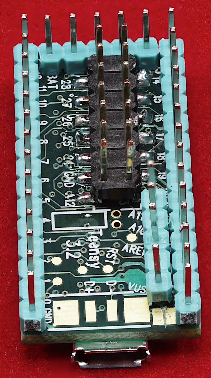
There are two additional 1x5 headers that need to be soldered onto the Teensy 3.2 board: the back row (DAC/A14, Program, Gnd, 3.3V, and VBat) and the four pins (in a 1x5 footprint, with the second pin removed [I use needle-nose pliers to pull the pin out]; VUSB, AREF, A10, and A11). It is important (especially with the header on the end of the Teensy) to ensure these pins line up properly with the pins already installed. In particular, the 1x5 header on the back should line up with pins 12 & 13. If these pins are not lined up properly, you will have difficulty attaching the Teensy 3.2 to the EWB PCB.
Now it’s time to attached the Teensy 3.2 to the Ethernet Watchdog Board. If you are really brave and confident in your assembly abilities, you can solder the Teensy directly to the EWB PCB. I do not recommend this as once you do this, you will probably not be able to remove the Teensy 3.2 without damaging it (a heat gun applied to the back of the PCB is the only way to get it off, and the heat necessary to remove the Teensy will likely cause unintended solder flows on the Teensy 3.2 board, itself). However, if you are really, really, brave (and this is a production run), then soldering the Teensy directly to the board is certainly an option. Of course, soldering the Teensy directly to the board will produce a more reliable connection (which may be important if you are using the EWB in a safety-critical environment). However, at least for your first unit, I recommend socketing the Teensy 3.2.
If you are going to solder the Teensy 3.2 directly to the EWB PCB, this is your last chance to verify that you’ve cut the trace between the VIN and VUSB pads (see step 18). Once you solder the Teensy onto the PCB, it will be exceedingly difficult, if not impossible, to cut this trace. Note that the EWB requires this trace to be cut for proper operation. (For those who notice such things, the following picture, and other pictures in this section, use an older version of the EWB PCB; for the purposes of this discussion this matters not at all).
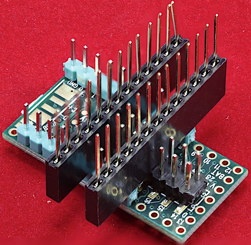
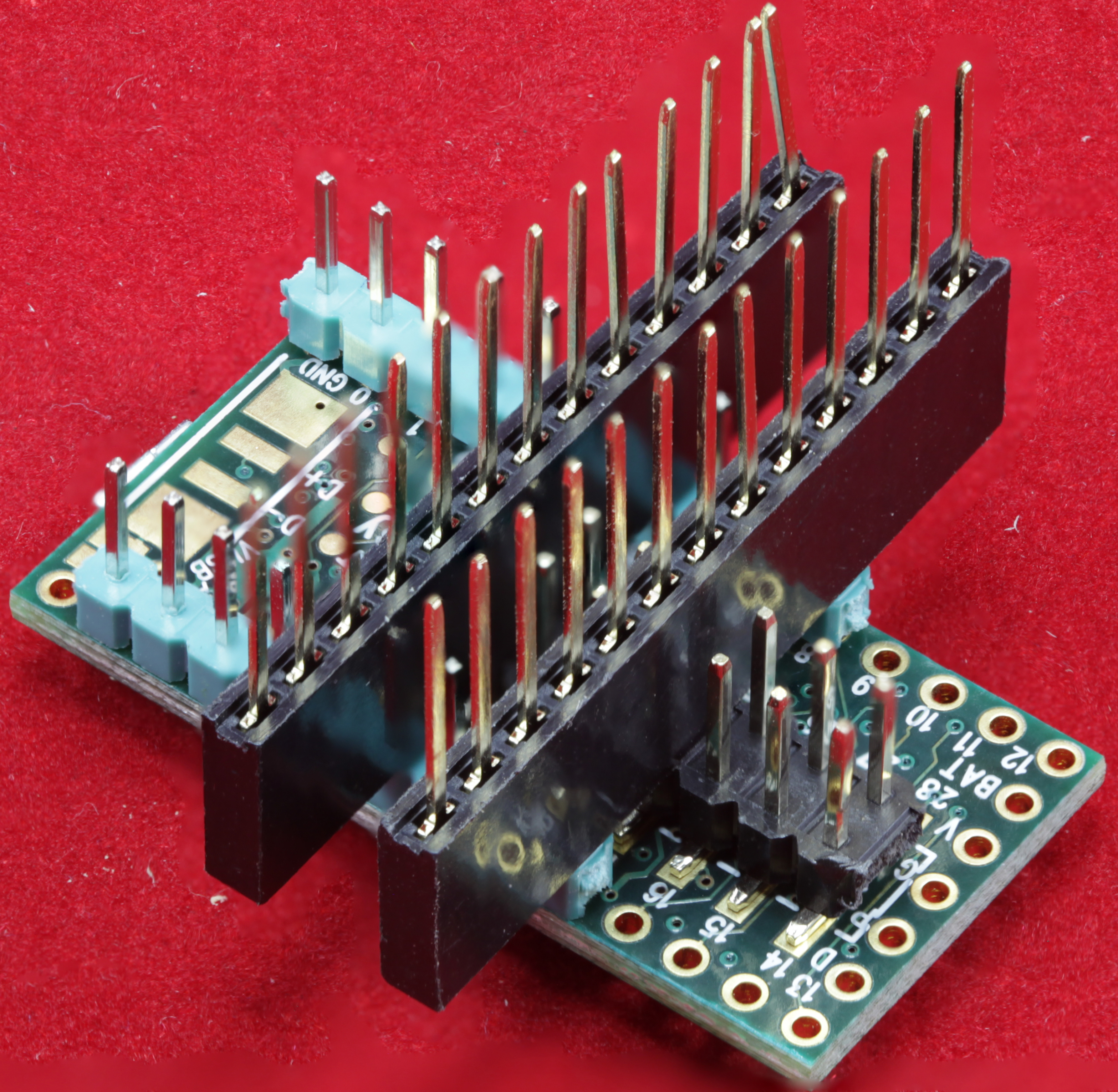
If you choose to socket the Teensy, you’re going to have to build the socket yourself, as there are no “off-the-shelf” sockets that match the Teensy 3.2’s footprint. I construct the Teensy socket from (2) 1x14 female headers, (2) 1x5 female headers, and (2) 1x7 female headers. Rather than trying to locate headers of these different sizes, I personally chose to purchase a batch of 1x40 female headers and I cut them down to size (using wire snippers), as needed. If you take this approach, be sure to carefully trim any excess plastic off one end of the two 1x7 headers and off both ends of one of the 1x5 headers. These “shaved” ends need to butt up against other headers and they one fit properly if there are any plastic protrusions. For the 1x7 headers, I just use an end of the 1x40 header so that it’s automatically flat. You can use an end of the 1x40 for the 1x5 header, but that will only take care of one end; you’ll still need to trim the other end down. The 1x5 header that you do not trim needs to have pin 2 removed (just pull it out with a pair of needle-nose pliers), as it goes into the four holes associated with VUSB, AREF, A10, A11, and A13.
I install these headers in the appropriate positions on the Teensy 3.2 (male) header pins (on the bottom of the board). This treats the Teensy as a soldering jig for installing the female headers onto the PCB board.
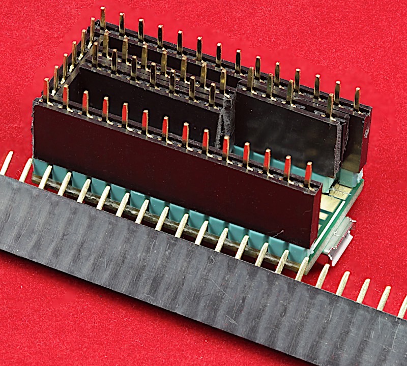
Insert the header pins into the Teensy 3.2. Turn the board over and verify that all pins are poking through the holes (that is, you haven’t bent any pins) prior to soldering the pins to the PCB. Solder all the pins onto the board.
By the way, were you to remove the Teensy 3.2 from the socket, the socket would look similar to the following:
Warning: The socket has a (very) limited insertion/removal lifetime. Each time you insert or remove a Teensy 3.2 into/from this socket, you increase the likelihood of reliability issues. The purpose of the socket is to allow you to easily remove the Teensy 3.2 (the most expensive component on the board and the one most difficult to remove) if the board does not work properly. This socket is not intended as a device to allow you to share the Teensy 3.2 amongst several different devices by swapping it around, as needed.
Installing the Feather bus headers
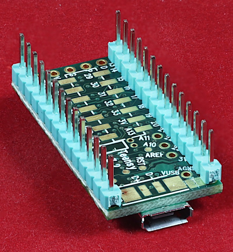
The last assembly step is to solder on the Adafruit Feather bus headers. If you’ve soldered the Teensy directly onto the PCB, this is a no-brainer – just solder the headers (1x16 and 1x12 pin female headers) onto the PCB. The Feather headers will provide sufficient clearance above the Teensy 3.2.
However, if you have socketed your Teensy 3.2, you will need to elevate the Feather headers to provide proper clearance above the (socketed) Teensy 3.2. To do this, use long-tailed Feather headers. To solder the headers properly, I recommend using a Featherwing adapter (such as the Ethernet Featherwing, which is the most likely device to plug into the Feather bus headers) as a soldering jig. Attach the Feather headers to the pins on the Featherwing device (as appropriate) and insert the pins into the Featherbus holes on the EWB PCB:
When soldering the pins onto the bottom of the board, be sure to keep them all at the same height so that the Feather bus is level:
To prevent shorts and make it easier to solder the Feather headers onto the EWB PCB, I personally have 3-D printed some standoffs for the headers:
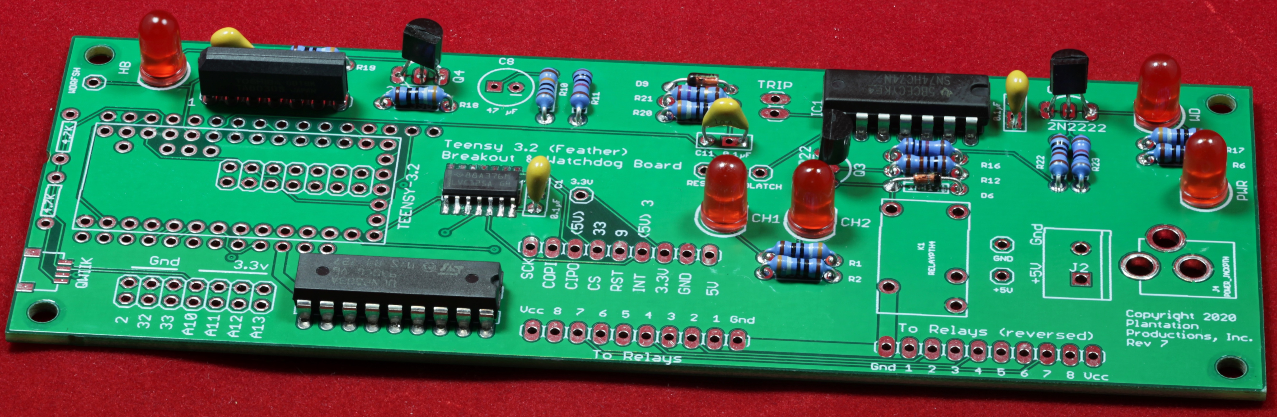
This completes the electronic assembly of the EWB PCB. The complete assembly of the EWB will conclude after the section on testing. You'll want to test the EWB before mounting it in its case (along with the 8-channel relay board).
Here are the links to the 3-D Printer STL files for the:
One Last Assembly Item
Before calling it quits, it's a real good idea to inspect each and every pin you've soldered on the EWB board. It's very easy to miss a few pins here and there.
Now that you've finished assembling the board, it's a good idea to spray some flux remover over all the solder joints and clean off the solder flux (mostly on the bottom of the board, but there are a few points on the top, such as the Teensy 3.2 module, that also have soldered joints with excess solder flux floating around).
For What It's Worth...
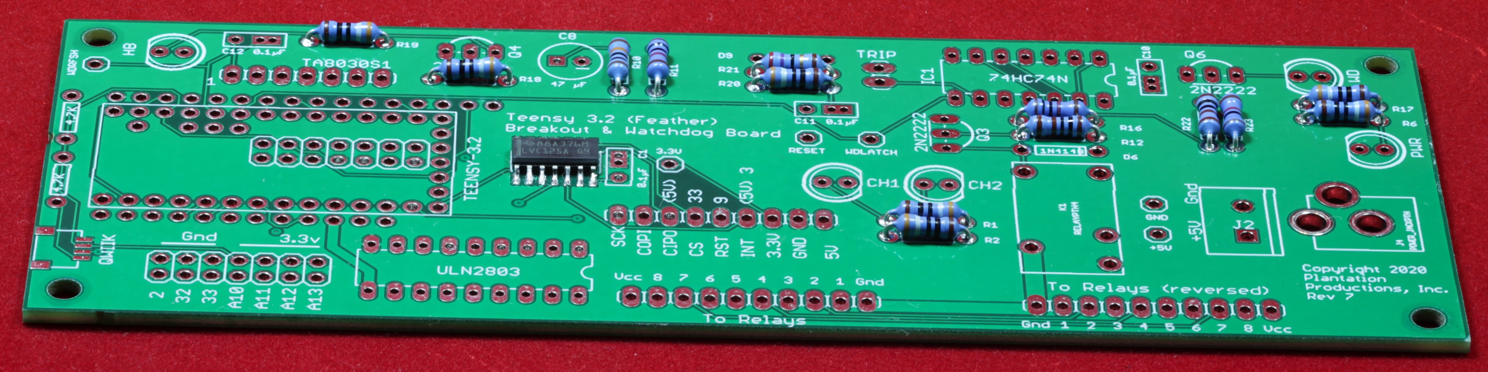
Most of the pictures in this assembly tutorial were shot using a Rev 7 version of the EWB. Many of the Teensy pin assembly photos were shot using Rev 4 of the PCB.
Testing the EWB
After you've soldered the last component onto the board, I'm sure you're itching to try it out. Sadly, chances are pretty good there are some mistakes made during assembly. Now comes the boring part -- testing your work to ensure that the board is working properly.
Note: The test code and firmware can be downloaded as a zip file from:
The Smoke Test
The very first test is the "smoke" test. This involves applying power to the EWB and verifying that it doesn't make a popping sound and doesn't produce a cloud of smoke as the unit self-destructs.
Seriously, though, when you apply power the "Pwr" LED should illuminate and if you've got a stock Teensy 3.2 module installed, the LED on the Teensy should be blinking on and off. The watchdog LED (and relay) may be doing funny things every 5 seconds or so, ignore that for now.
If the Pwr LED does not illuminate and the Teensy 3.2 LED is not blinking, test the 5V test point with a DVM (5V and Gnd should read around 5v).
If the Teensy LED is blinking but the Pwr LED is not, chances are you've installed the Pwr LED backwards (or it is defective, you did test it, right?). If the Pwr LED is lit and you've got 5V, but the Teensy LED is not blinking, either your Teensy isn't working properly or it doesn't have the stock "BLINK" sketch installed. Check all the solder connections on the bottom of the EWB (to the Teensy) and verify that there aren't any shorts.
Programming the EWB
Before going any further, you did cut the VUSB jumper, right? If not, it's still possible to do it (though a lot more difficult if you've soldered the Teensy to the EWB PCB as the pads are barely accessible between the Teensy and the EWB PCBs). You don't want to plug in a USB cable to the Teensy and power the EWB unless the jumper is cut (see the beginning of the assembly tutorial for more details). We'll start with the EWB version of the "BLINK" program. The EWB utility LED (also known as the "heartbeat" LED) is attached to pin 7. The following code is a modification of the standard Arduino BLINK sketch that toggles pin 7 rather than pin 13. This version also contains code to reset the watchdog latch on power up and refresh it every couple of seconds to avoid having the watchdog LED light up.
/*
  Blink (EWB version)
  Turns on an LED on for one second, then off for one second, repeatedly.

  This example code is in the public domain.
 */

// Pin 13 has an LED connected on most Arduino boards.
// Pin 11 has the LED on Teensy 2.0
// Pin 6  has the LED on Teensy++ 2.0
// Pin 13 has the LED on Teensy 3.0
// Pin 7 is the Heartbeat LED on the EWB board
// give it a name:

int led = 7;


#define eth_reset   (9)
#define wd_rfsh     (22)
#define wd_latch    (21)
#define Reset       (23)


// Must send a positive pulse to the TA8030s
// to refresh the watchdog timer:

void watchdogRefresh( void )
{
    digitalWrite( wd_rfsh, 1 );
    delay( 1 );
    digitalWrite( wd_rfsh, 0 );
}

// Must send a negative-going pulse to the DS1834
// chip to cause a reset. The pulse must be at least
// 350 msec wide.

void toggleReset( void )
{
        digitalWrite( Reset, 0 );
        delay( 350 );
        digitalWrite( Reset, 1 );
}

// the setup routine runs once when you press reset:

void setup()
{
    // initialize the digital pin as an output.
    pinMode(led, OUTPUT);

    // Stuff needed by the watchdog timer:

    pinMode( Reset, OUTPUT );       // Reset pin is an output
    pinMode( wd_rfsh, OUTPUT );     // Watchdog refresh is an output
    toggleReset();                  // Reset watchdog timer latch.
    watchdogRefresh();              // Must do this at least once every 4.7 seconds

}

// the loop routine runs over and over again forever:

void loop()
{
    digitalWrite(led, HIGH);    // turn the LED on (HIGH is the voltage level)
    delay(1000);                // wait for a second
    digitalWrite(led, LOW);     // turn the LED off by making the voltage LOW
    delay(1000);                // wait for a second

    // Refresh the watchdog timer every 2 seconds:

    watchdogRefresh();          // Must do this at least once every 4.7 seconds
}
Note: pin 13 on the Teensy 3.6 will control the Teensy 3.6's on-board LED. However, the Adafruit Feather bus also uses this pin for the SPI clock output so you shouldn't use this pin as an LED control if you're using the SPI features on the Feather bus.
Testing the Watchdog Timer
Download code in electronic form
The following sketch starts by resetting (and refreshing) the watchdog timer. Then it allows the watchdog timer to expire and verifies that the watchdog latch remains open. Finally, it verifies that after the watchdog is reset, it will expire again if it is not refreshed.
/*
  WatchdogTest (EWB version)
  Verifies the proper operation of the EWB hardware watchdog timer

  This example code is in the public domain.
 */

#define eth_reset	(9)
#define wd_rfsh     (22)
#define wd_latch    (21)
#define Reset       (23)

unsigned long	startTimer;
unsigned long	curTimer;
unsigned		latch;
int				latchFailure	= false;
int				wdFailure 		= false;
int				testDone 		= false;


// Must send a positive pulse to the TA8030s
// to refresh the watchdog timer:

void watchdogRefresh( void )
{
    digitalWrite( wd_rfsh, 1 );
    delay( 1 );
    digitalWrite( wd_rfsh, 0 );
}

// Must send a negative-going pulse to the DS1834
// chip to cause a reset. The pulse must be at least
// 350 msec wide.

void toggleReset( void )
{
        digitalWrite( Reset, 0 );
        delay( 350 );
        digitalWrite( Reset, 1 );
}

// the setup routine runs once when you press reset:

void setup()
{

    Serial.begin( 9600 );

    // Stuff needed by the watchdog timer:

    pinMode( Reset, OUTPUT );       // Reset pin is an output.
    pinMode( wd_rfsh, OUTPUT );     // Watchdog refresh is an output.
    pinMode( wd_latch, INPUT );    // Read watchdog state here.

    delay( 1000 );
    Serial.println( "Watchdog test program" );

    watchdogRefresh();              // Guarantee that the WD is refreshed
    toggleReset();                  // Reset watchdog timer latch.
    delay(500);						// Give relay time to open, etc.
    toggleReset();                  // Reset watchdog timer latch.
    delay(500);						// Give relay time to open, etc.
    watchdogRefresh();              // Guarantee that the WD is refreshed
    delay( 100 );
    latch = !digitalRead( wd_latch );
    if( latch )
    {
    	Serial.println( "WD Latch failed to clear after reset/refresh" );
    	latchFailure = true;
    }
    startTimer = millis();			// Time at start of timeout period

}

// the loop routine runs over and over again forever:

void loop()
{
	curTimer = (millis() - startTimer);
	if(  curTimer == 6000 && digitalRead( wd_latch ) && !wdFailure)
	{
		Serial.println( "Watchdog timer failed to expire" );
		wdFailure = true;
	}
	if( curTimer == 6001 && !digitalRead( wd_latch ) )
	{
		toggleReset();
		delay( 350 );
		if( !digitalRead( wd_latch ))
		{
			Serial.println( "Failed to reset watchdog timer" );
		}
	}
	if( curTimer >= 10000 && !testDone )
	{
		if( !digitalRead( wd_latch ))
		{
			Serial.println( "Watchdog timer failed to expire, again" );
		}
		Serial.println( "Watchdog test complete" );
		testDone = true;
	}

}
Testing the Relay Outputs
Download code in electronic form
The following sketch starts by resetting (and refreshing) the watchdog timer. Then it cyles through a sequence where it:
- Turns on and off each of the relays (K1 through K8) in sequence,
- Turns on and off the set of four relays {K1-K4} followed by {K5-K8},
- Turns off all relays,
- Turns on all relays,
- Turns off all relays,
- Repeats each of these steps.
Before running this test, you should connect an 8-channel relay board to the EWB (to the "To Relays" connector). Ensure that the cable connection connects corresponding signals between the EWB and relay board.
Once the test successfully completes, remove the cable from the "To Relays" connector, turn it around, and attach it to the "To Relays (Reversed)" connector. The repeat the test.
// Ethernet Watchdog Board // Relay Test // Randall Hyde // // This example code is in the public domain. #include#include // Pin 7 is the Heartbeat LED on the Ethernet WD board // give it a name: int led = (7); #define eth_reset (9) #define wd_rfsh (22) #define wd_latch (21) #define Reset (23) // Eight output pins connected to ULN2803 Darlington array. // Note: Pins are reversed to improve the PCB layout. // Relay outputs: #define out0 (24) #define out1 (25) #define out2 (26) #define out3 (27) #define out4 (28) #define out5 (29) #define out6 (30) #define out7 (31) // Turn off all the digital outputs: void clearAll( void ) { digitalWrite( out0, 0 ); digitalWrite( out1, 0 ); digitalWrite( out2, 0 ); digitalWrite( out3, 0 ); digitalWrite( out4, 0 ); digitalWrite( out5, 0 ); digitalWrite( out6, 0 ); digitalWrite( out7, 0 ); } // Must send a positive pulse to the TA8030s // to refresh the watchdog timer: void watchdogRefresh( void ) { digitalWrite( wd_rfsh, 1 ); delay( 1 ); digitalWrite( wd_rfsh, 0 ); } // Must send a negative-going pulse to the TA8030S // chip to cause a reset. The pulse must be at least // 350 msec wide. void toggleReset( void ) { digitalWrite( Reset, 1 ); delay( 500 ); digitalWrite( Reset, 0 ); delay( 500 ); digitalWrite( Reset, 1 ); } // the setup routine runs once when you press reset: void setup() { byte latch; // Initialize the Ethernet featherwing: Serial.begin( 9600 ); while(!Serial); // Wait for serial port to come up. Serial.println( "Plantation Productions' EWB relay test" ); // Initialize the LED digital pin as an output. pinMode(led, OUTPUT); // Digital output lines -- always outputs: pinMode( out0, OUTPUT ); pinMode( out1, OUTPUT ); pinMode( out2, OUTPUT ); pinMode( out3, OUTPUT ); pinMode( out4, OUTPUT ); pinMode( out5, OUTPUT ); pinMode( out6, OUTPUT ); pinMode( out7, OUTPUT ); clearAll(); // Assume time-out (failsafe) on startup. // Stuff needed by the watchdog timer: pinMode( eth_reset, OUTPUT ); // Ethernet reset pin is an output pinMode( Reset, OUTPUT ); // Reset pin is an output pinMode( wd_rfsh, OUTPUT ); // Watchdog refresh is an output pinMode( wd_latch, INPUT ); // Watchdog Latch is an input // Loop until we've reset the watchdog timer and read a "watchdog latch // not set" signal from the watchdog timer. do { toggleReset(); // Reset watchdog timer latch. watchdogRefresh(); // Must do this at least once every 4.7 seconds latch = digitalRead( wd_latch ); #if useSerialPort if( !latch ) { Serial.println( "Watchdog latch not cleared, resetting" ); } #endif }while( !latch ); } // the loop routine runs over and over again forever: void loop() { static unsigned long lastSecs = 0; static unsigned long seconds = 0; static unsigned long lastTime = 0; static byte ledState = 0; static int relayState = 0; static int relayVal[8] = {0, 0, 0, 0, 0, 0, 0, 0}; unsigned long curTime = millis(); // Every 1/2 second invert the LED and // refresh the watchdog timer. if( abs( curTime - lastTime ) >= 1000 ) { digitalWrite(led, ledState); ledState = !ledState; watchdogRefresh(); lastTime = curTime; // If the EWB watchdog timer has timed out, // reset it (because we're obviously running). byte latch = digitalRead( wd_latch ); if( !latch ) { #if useSerialPort Serial.println( "Watchdog latch clear, resetting" ); #endif setup(); // Reset everything } ++seconds; } // Every two seconds, change the relay state: if( seconds != lastSecs ) { Serial.print( "Relay State=" ); Serial.println( relayState ); memset( relayVal, 0, sizeof relayVal ); switch( relayState ) { case 0: case 1: case 2: case 3: case 4: case 5: case 6: case 7: relayVal[ relayState ] = 1; break; case 8: relayVal[0] = 1; relayVal[1] = 1; relayVal[2] = 1; relayVal[3] = 1; break; case 9: relayVal[4] = 1; relayVal[5] = 1; relayVal[6] = 1; relayVal[7] = 1; break; case 10: // All Relays Off break; case 11: relayVal[0] = 1; relayVal[1] = 1; relayVal[2] = 1; relayVal[3] = 1; relayVal[4] = 1; relayVal[5] = 1; relayVal[6] = 1; relayVal[7] = 1; break; case 12: // All Relays Off break; } digitalWrite( out0, relayVal[0] ); digitalWrite( out1, relayVal[1] ); digitalWrite( out2, relayVal[2] ); digitalWrite( out3, relayVal[3] ); digitalWrite( out4, relayVal[4] ); digitalWrite( out5, relayVal[5] ); digitalWrite( out6, relayVal[6] ); digitalWrite( out7, relayVal[7] ); lastSecs = seconds; relayState = (relayState + 1) % 13; } }
Testing the Ethernet Watchdog
This test assumes the use of the Adafruit Ethernet Featherwing attached to the Feather bus connectors on the EWB.
The following tables describe the I/O pinouts on the Feather bus.
| Pin | Digital I/O Pin | Feather JP3 Header Function |
|---|---|---|
| 1 | -- | Gnd |
| 2 | 1 | TX1 |
| 3 | 0 | RX1 |
| 4 | 12 | MISO0 |
| 5 | 11 | MOSI0 |
| 6 | 13 | SCK0 |
| 7 | 20 | A6 (analog input 0-3.3V) |
| 8 | 14 | A0 (analog input 0-3.3V) |
| 9 | 16 | A2 (analog input 0-3.3V) |
| 10 | 17 | A3 (analog input 0-3.3V) |
| 11 | 15 | A1 (analog input 0-3.3V) |
| 12 | -- | DAC0 |
| 13 | -- | Gnd |
| 14 | -- | ARef |
| 15 | -- | 3.3v supply (max 250mA) |
| 16 | -- | Program |
Note: JP3 Pin 1 (Gnd) is located on the lower-right hand side of the EWB PCB when viewed from the top.
JP4 Pin 1 is closest to the utility LED (labeled "LED") on the EWB PCB
| Pin | Digital I/O Pin | Feather JP4 Header Function |
|---|---|---|
| 1 | VBat | |
| 2 | -- | N/C |
| 3 | -- | Vcc (3.3v) |
| 4 | 5 | Digital I/O pin 5 (3.3v only) |
| 5 | 6 | Digital I/O pin 6 (3.3v only) |
| 6 | 9 | Digital I/O pin 9 (3.3v only) |
| 7 | 10 | Digital I/O pin 10 (3.3v only) |
| 8 | 4 | Digital I/O pin 4 (3.3v only) |
| 9 | 3 | Digital I/O pin 3 (3.3v only) |
| 10 | 8 | Digital I/O pin 8 (3.3v only) |
| 11 | 19 | SCL0 (3.3v, with 10K pullup to +3.3v) |
| 12 | 18 | SDA0 (3.3v, with 10K pullup to +3.3v) |
To test the Ethernet watchdog operation, I use a Windows program called "Hercules" (which you can download from https://hercules-setup.soft32.com). To test the Ethernet operation of the EWB, you will need to connect your EWB to an Ethernet network (via a switch) that has a (Windows) PC with the following attributes:
- IP Address of the PC must be 192.168.2.xxx (where "xxx" is not 19).
- IP Address mask is 255.255.255.0.
Install the EWB firmware on the EWB. After powering up, the relays should all be energize for a few seconds (4.7, typically) and then will go off as there is no refresh command coming across the Ethernet port. The heartbeat LED should be blinking at a 1/2-second period.
Run the Hercules application (or some other program capable of sending data to 192.168.2.19:20560 and 192.168.2.19:20561), select the TCP Client tab, and enter IP Address 192.168.2.19 and port 20560.
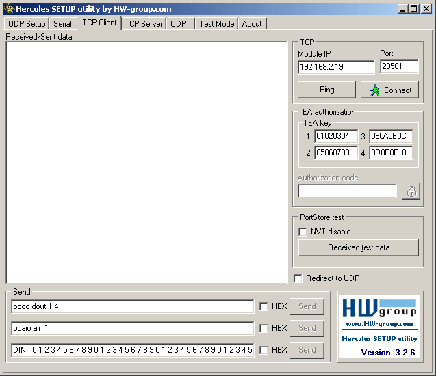
Press the connect button to connect to the EWB. Verify that the connection is made to the EWB:

Put the cursor in the "Received/Sent data" window and press any key. If everything is working properly, this should send the character to port 20560 on the EWB which should energize relays K5-K8. As long as you send a character within 4.7 seconds, the relays should remain energized.

Note that the EWB never returns any data on the Ethernet connection. There will be no indication in the Hercules window that the watchdog timer has been reset.
Press the disconnect button in the Hecurles Window. Change the port number to 20561 and reconnect to the EWB. Now, pressing a key should activate relays K1-K4
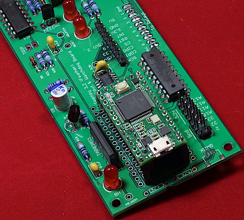
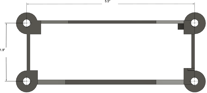
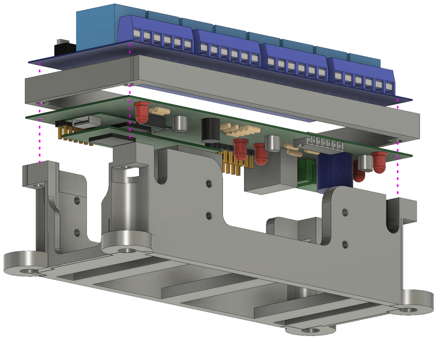
Final EWB Assembly (EWB + Relay board + stand)
The last step in the EWB assembly process is to mount the EWB and 8-channel Relay board onto the mounting stand. The completed assembly looks like this:
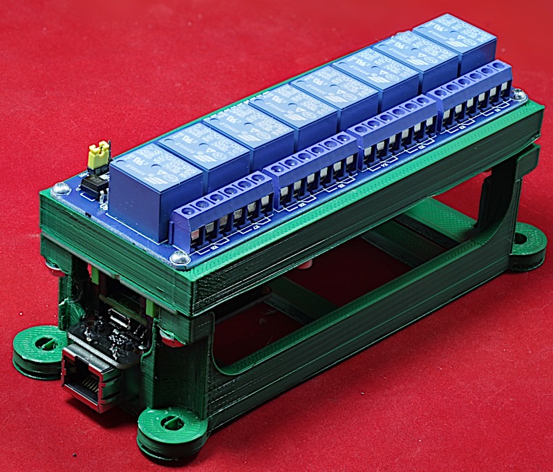
The EWB case/stand consists of two 3D-printed components: a coupler and a base (STL files: EWB 3D printer files):
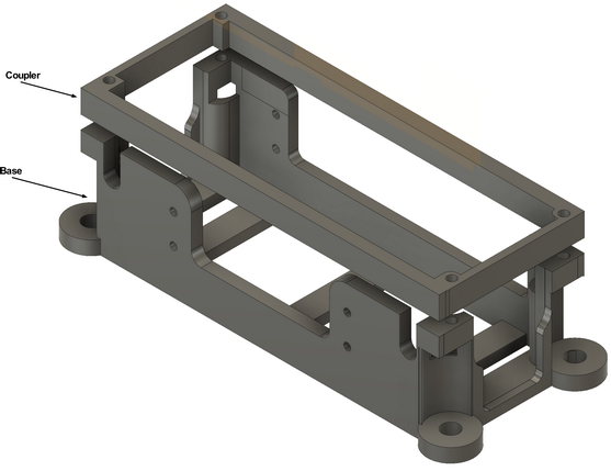
The EWB itself mounts upside down between the base and the coupler. The relay board mounts right-side up between the couple and the Ethernet Adapter Mounts on the Feather bus sockets on the EWB.
There are four 0.2” mounting holes on the base you can use to mount the entire unit to a flat surface. Four #8 bolts and nuts (with appropriate washers) will work fine for this purpose.
The important thing to note when assembling the boards on the stand is that the 1x10 headers on the two boards must be on the same side of the coupler.
Programming the EWB
This section is a recap of several of the programming examples appearing earlier in this document.
Reset
Programming a low pulse on the reset output pin will send a reset signal to the hardware watchdog timer. You must program this pin low for at least 250 msec. The reset signal has the following effects throughout the system:
- Resets the watchdog timer. Note that this is the only way to reset the watchdog timer latch. Therefore, you should always send a reset pulse when the system first powers up.
The reset line is digital I/O pin #23 on the Teensy 3.2:
#define Reset	 	23

// In setup function:

    pinMode( Reset, OUTPUT );

// Elsewhere:

void toggleReset( void )
{
		digitalWrite( Reset, 0 );
		delay( 250 );
		digitalWrite( Reset, 1 );
}
Watchdog Refresh
Programming a rising edge on the WD_RFSH output pin will refresh the EWB's on-board watchdog timer hardware. You must program at least one pulse every five seconds (or faster) to prevent the watchdog timer from "timing out" and activating the watchdog timer relay.
The reset line is digital I/O pin #22 on the Teensy 3.2:
#define wd_rfsh     22

// In setup function:

    pinMode( wd_rfsh, OUTPUT );


// Elsewhere:

// Must send a positive pulse to the TA8030s
// to refresh the watchdog timer:

void watchdogRefresh( void )
{
    digitalWrite( wd_rfsh, 1 );
    delay( 1 ); // A full millisecond isn't really needed, but it doesn't hurt
    digitalWrite( wd_rfsh, 0 );
}
Watchdog Latch Input
The watchdog latch input pin gives you an indication of the current watchdog timeout state. If you read a '1' on this input pin, then the watchdog timer has latched the "timeout" state. If you read a '0' on this pin, the watchdog timer has not timed out.
Note that once the watchdog timer times out, the watchdog timeout state is latched until the software explicitly resets it. Note that refreshing the watchdog timer once it has timed out will not reset the watchdog timer. You must pulse the reset signal (as noted above) to reset the watchdog timer.
#define wd_latch    21

// In setup function:

    pinMode( wd_rfsh, INPUT );


// Elsewhere:


latchStatus = digitalRead( wd_latch );
IRQ Input
The IRQ input signal is connected to the INT lines passed to the Ethernet interface. If you write your own Ethernet control software for the Arduino, you can program this pin (Teensy pin 3) as an interrupt signal. Note that nether the (standard) Arduino/Teensy Ethernet library code, nor the EWB firmware, make use of this pin.
Digital and Analog I/O Pins
The EWB brings out seven (otherwised unused) pins to a 2x7 header.
You can program these pins using standard Arduino function calls (digitalRead, digitalWrite, analogRead, etc.).
LED Control
The Teensy 3.2, like most Arduino-compatible CPU boards, connects an on-board LED to digital output pin 13. Unfortunately, pin 13 is also used for SCK0 (the SPI clock on the Feather bus). If you're not using the Feather bus (or the SPI connector on it) then you can program the Teensy's LED by writing a one or zero to this pin. However, if you are using the SPI bus, this function is not available. For this reason, the EWB includes an LED (and appropriate transistor driver) connected to digital output pin 7 on the Teensy 3.2. Writing a 1 to this pin turns the LED on, writing a zero turns the LED off.
Adafruit Feather-Compatible Bus
The EWB includes a pair of headers that implement Adafruit's Feather bus (as implemented on their Teensy 3.2 Feather Adapter). The pinouts for these two (female) headers is the following:
| Feather Pin # | Name | JP3 Description |
|---|---|---|
| 1 | VBat | A 3V coin cell battery between this pin and ground provides power for the Teensy 3.6's RTC. |
| 2 | N/C | Not available on the Teensy Feather. |
| 3 | Vcc | 5V source from EWB power supply |
| 4 | GPIO pin 5 | Digital I/O line corresponding to pin 5 on the Teensy |
| 5 | GPIO pin 6 | Digital I/O line corresponding to pin 6 on the Teensy |
| 6 | GPIO Pin 9 | Digital I/O line corresponding to pin 9 on the Teensy |
| 7 | GPIO Pin 10 | Digital I/O line corresponding to pin 10 on the Teensy |
| 8 | GPIO Pin 4 | Digital I/O line corresponding to pin 4 on the Teensy |
| 9 | GPIO Pin 3 | Digital I/O line corresponding to pin 3 on the Teensy |
| 10 | GPIO Pin 8 | Digital I/O line corresponding to pin 8 on the Teensy |
| 11 | SCL0 | I2C clock line |
| 12 | SDA0 | I2C data line |
Note: Pin 1 on the small Feather header is the pin closest to the middle of the Teensy 3.6 module.
| Feather Pin # | Name | JP4 Description |
|---|---|---|
| 1 | Gnd | Signal ground |
| 2 | Tx1 | Serial 1 transmit signal (3.3V, not RS-232 compatible) |
| 3 | Rx1 | Serial 1 receive signal (3.3V, not RS-232 compatible) |
| 4 | MISO0 | Teensy 3.6 SPI bus #0, MISO signal |
| 5 | MOSI0 | Teensy 3.6 SPI bus #0, MOSI signal |
| 6 | SCK0 | Teensy 3.6 SPI bus #0, clock signal |
| 7 | A6 | Teensy 3.5 ADC #6 |
| 8 | A0 | Teensy 3.5 ADC #0 |
| 9 | A3 | Teensy 3.5 ADC #3 |
| 10 | A2 | Teensy 3.5 ADC #2 |
| 11 | A1 | Teensy 3.5 ADC #1 |
| 12 | DAC0 | Teensy 3.6 DAC #0 output (note: pin can be reprogrammed) |
| 13 | Gnd | Signal ground |
| 14 | ARef | Reference voltage for Teensy 3.6 ADC (see Teensy documentation for limits) |
| 15 | 3.3V supply | 3.3V, maximum 250ma, from the Teensy 3.6 module (voltage regulator on Teensy) |
| 16 | Program | Teensy 3.6 PROGRAM signal |
Note: Pin 1 on the large Feather header is the pin farthest from the EWB PCB.
Note that the Feather pins are connected directly to the Teensy 3.2 with no level shifting or buffering (just as with the Teensy 3.2 module). All signals are 3.3V only! As all (commercially available) Featherwings are designed for 3.3V systems, this shouldn't be an issue unless you develop your own Featherwings or just plug wires directly into the Feather headers.
Of course, most pins on the Teensy 3.2 are function reprogrammable, so it's quite possible for you to change an analog input to a digital I/O pin or a digital I/O pin to an analog input. See the Teensy 3.2 documentation for more details.