
Note: All photographs appearing on this page are freely usable for any purpose. Links to high-resolution versions of the pictures appear below each picture.
Digital Data Acquisition & Control System
PPAC420
8-Channel 4-20 mA to 5V conversion
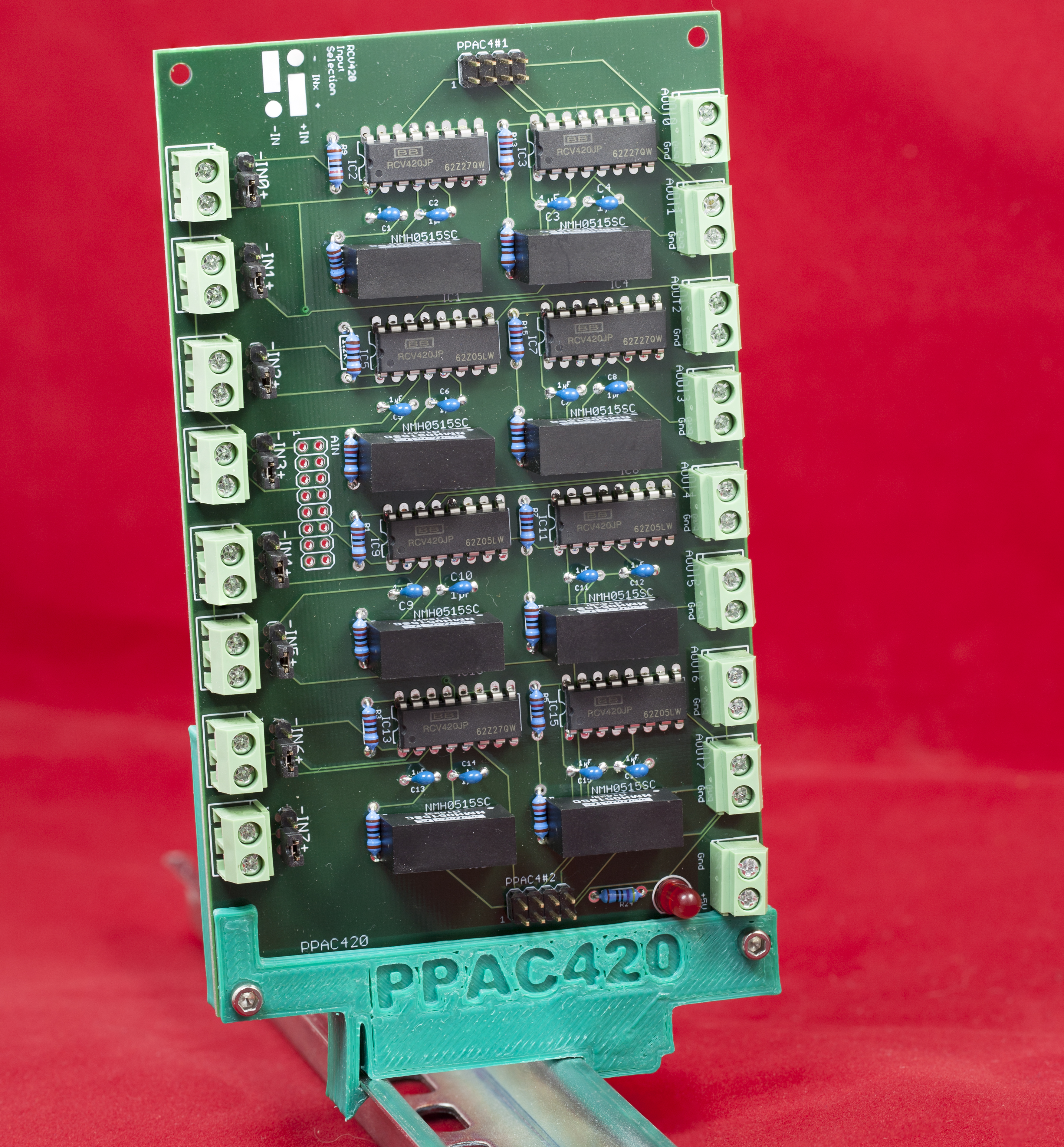
High-resolution image shot with a Canon EOS 5D MII (Shown with vertical DIN Rail mount)
The PPAC420 board is an 8-channel 4-20mA conversion board. It converts an input current loop source in the range 0-20mA to a voltage in the range -1.25 to 5.0V (4mA produces 0V). The output from the board is suitable as an input to a PPAC4 analog conditioning board (which accepts ±10V as the input signal and produces differential/double-ended outputs suitable as inputs to the PPAIO-16/4 analog I/O board).
The PPAC420 has the following feature set:
- Open Hardware design based on Creative Commons 4.0 license
- Runs off a single +5V power supply (two-pin screw terminals)
- LED indicates when power is applied to the board
- Eight independent and isolated channels
- 4 mA input produces 0V output; 20 mA input produces 5V output (0 to 4mA produces a negative voltage in the range -1.25V to 0V)
- If the (singled-ended) outputs are provided as inputs to a PPAC4 module, then each circuit is completely isolated all the way through the DAQ system
- On board 5V to ±15V isolation power supplies provide independent, isolated power for each RCV420 current loop receiver IC
- Jumper-selectable between plus and minus current input
- Eight sets of two-pin screw terminals provide current source input
- A 16-pin (2x8) header provide alternate input (via ribbon cable) for all eight inputs
- Eight sets of two-pin screw terminals provide voltage outputs for each channel
- Two 8-pin (2x4) headers provide ribble cable connections to matching connectors on PPAC4 board
- DIN rail mounts allow the board to be optionally mounted in a vertical or horizontal orientation on a 35mm DIN rail
- Schematic and board layout are available in Eagle format
- DIN rail brackets are available in .STL format for 3D-printing
- Full documentation including System Requirements Specifications (SyRS), Hardware Requirements Specifications (HRS), Hardware Inspection list (HI), Hardware Test Cases (HTC), Hardware Test Procedures (HTP), Hardware Design Description (HDD), and (reverse) Traceability Matrix (RTM) are available for the DAQ system, including this board.
PPAC420 Bill of Materials (BOM)
- (1) 5mm LED
- (16) 1 µF decoupling capacitors
- (16) 1.2 kΩ 1/4-watt 1% resistors
- (1) 470 Ω 1/4-watt 1% resistor
- (1) 16-pin (2x8) male header (ribbon cable connector)
- (2) 8-pin (2x4) male header (ribbon cable connector)
- (8) 3-pin (1x3) male header (jumpers)
- (12) 4-pin (2x2) male headers
- 8 2-pin jumpers
- (8) RCV420 current loop receiver ICs
- (8) NMH0515SC isolation power supplies (DC 5V to ±15V)
- (17) Two-terminal screw terminals (5mm/0.2" centers)
- (1) PPAC420 PCB
- Optional: one set of horizontal 35mm DIN rail mounts for DAQ boards
- Optional: one PPAC420 vertical 35mm DIN rail mount
Note: If you only want a few PPAC420 PCBs, contact Plantation Productions (randy@plantation-productions.com) to see if there are any in stock. Bare boards are $25 each plus shipping; fully assembled and tested boards are $499. If you need more than a couple and you're not in a huge hurry, it costs about $150 (plus about 4-6 weeks) to have a set of 10 manufactured and shipped to you from China. I use Seeed Studio Fusion PCD service (https://www.seeedstudio.com/fusion.html). The PPAC420 PCBs are four-layer boards. Here are the Gerber files for them (provide these files to Seeed Studio or your personal PCB manufacturer).
If you want to modify or enhance the PPAC420 design, or re-layout the PCB using Eagle, here are the Eagle files:
PPAC420 Eagle files (Schematic and board layout)
If you simply want to view the schematic on-line, you'll find that here:
The DIN rails were created using AutoDesk's Fusion 360 (to produce STL files) and I personally print the results on a Lulzbot Taz6 3D printer using ABS filament (ABS is recommended for this job, PLA and PETG are a bit brittle). The STL files can be found here:
PPAC420 DIN Rail Brackets (Horizontal) 3D printer files
PPAC420 DIN Rail Brackets (Vertical) 3D printer files
PPAC420 Board Layout
Connecting a PPAC420 board to a DAQ System (via PPAC4 and PPAIO-16/4)
The PPAC420 board outputs a voltage in the range -1.25V (0mA) through 0V (4mA) to 5V (20 mA). Because the voltage range is -1.25V to +5V, you must pass this signal through one channel on a PPAC4 signal conditioning board to produce a differential signal that is compatible with the PPIO-16/4 analog inputs. Because there are 8 channels on a PPAC420 and only 4 channels on a PPAC4, you will need to connect two PPAC4 boards between the PPAC420 and PPAIO-16/4 boards.
Wiring can be done using point-to-point wiring via the two-conductor screw terminals (AOUT0 to AOUT7) on the PPAC4 and the corresponding two-conductor screw terminals on the PPAC4 boards (AIN0 to AIN3 on board #1 and AIN0 to AIN3 on board #2). As an alternative, you can use 8-conductor (2x4 IDC header) ribbon cables to connect the PPAC420 to two separate PPAC4 boards. Then you can connect those two PPAC4 boards to a single PPAIO-16/4 board:
Calibrating the PPAC420 Board
The PPAC420 board does not provide any calibration facilities. Instead, you perform all calibration on the PPAC4 board. See the PPAC4 web page for calibration details. Because the PPAC420 produces a voltage output in the range -1.25V to +5V, you should calibrate the PPAC4 channels to accept a ±10V range. Then program the PPAIO-16/4 board with a gain setting of two (0 to 2.048V input). This will, effectively, double the voltage range of the PPAC420 (to the range -2.5V to +10V) and give you the maximum precision during analog to digital conversions.
Isolated Inputs
The PPAC420 board has eight independent circuits that perform the 4-20mA to voltage conversion. Each channel includes an isolated power supply, so the eight channels are independent of one another. The outputs are fed into the inputs of the PPAC4 board, which has an isolation amplifier on the input. Therefore, each PPAC420 is isolated from the rest of the DAQ system as well as from the other PPAC420 channels. Note that the RCV420 and LM324 ICs on each 4-20mA channel are not isolated from the input, so if a huge spike or other big signal came along these two chips could be damaged; the rest of the system, however, is protected by the ISO122 isolation amplifier on the PPAC4 board.
Programming the PPAC420 Board
The PPAC420 board is pure hardware. There is no PPAC420-specific software programming possible. The PPAC420 connects to the PPAIO-16/4 board (via the PPAC4 board) and the software controls the ADCs (and DACs) on that board. Therefore, programming the PPAC420 consists of programming PPAIO-16/4 board. See the web page on the PPAIO-16/4 board for more details.