CBU Theater Port Hole
A 3D Printer/Vacuum molding project

Note: All photographs appearing on this page are freely usable for any purpose. Links to high-resolution versions of the pictures appear below each picture.
High-resolution image shot on Canon EOS 5D MkII
Port Hole Project
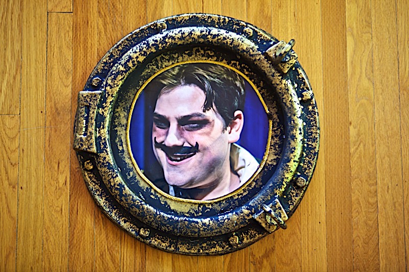
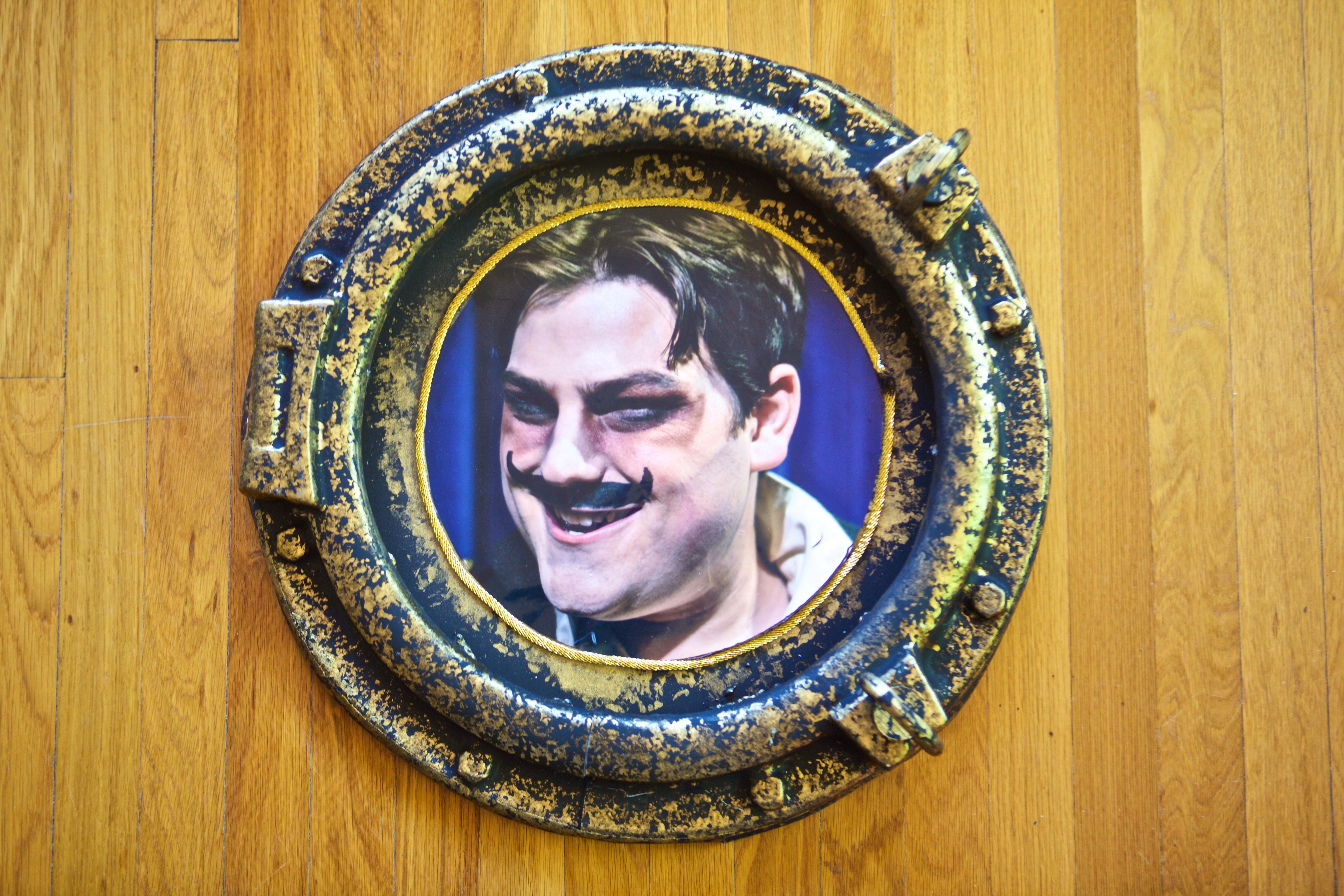
The theater department at California Baptist University (CBU) needed 24 ship "port holes" made for one of their productions. They purchased a novelty mirror that had the shape they wanted and they converted the frame for the mirror (the port hole) into a "buck" (basically the opposite of a "mold") we could use to create vacuum-formed copies. The vacuum forming project was done on the vacuum-forming machine at Vocademy, that could handle 2'x3' sheets of 0.030" thick high-impact styrene.
3D Printing Component
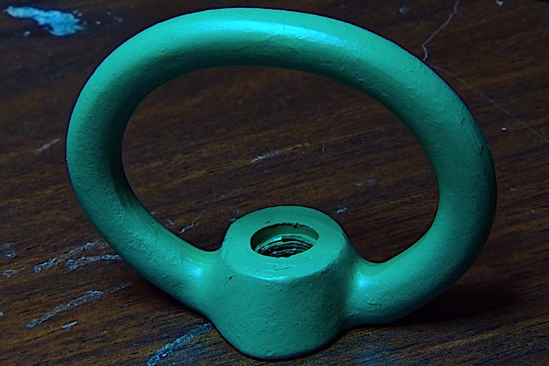
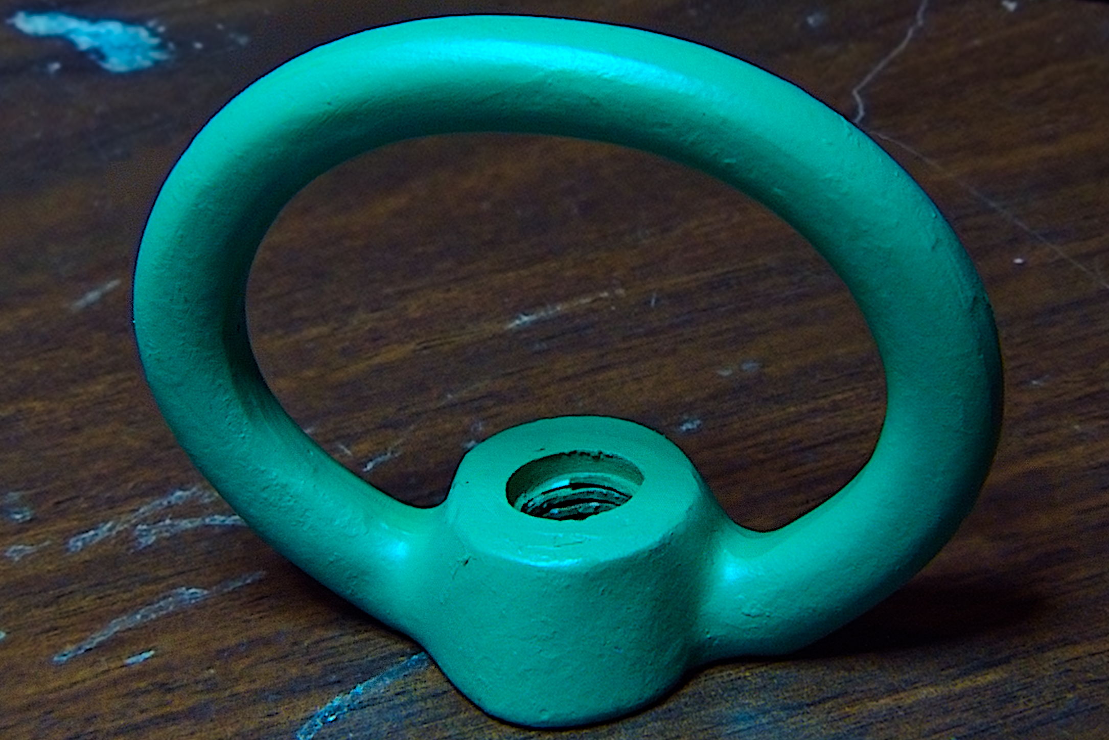
There were two "latches" on the port hole that could not be formed during the vacuum-forming process. I created a 3D model using Fusion 360 to provide a similar-looking device.
Here's the original:
High-resolution image shot on Lytro Illum
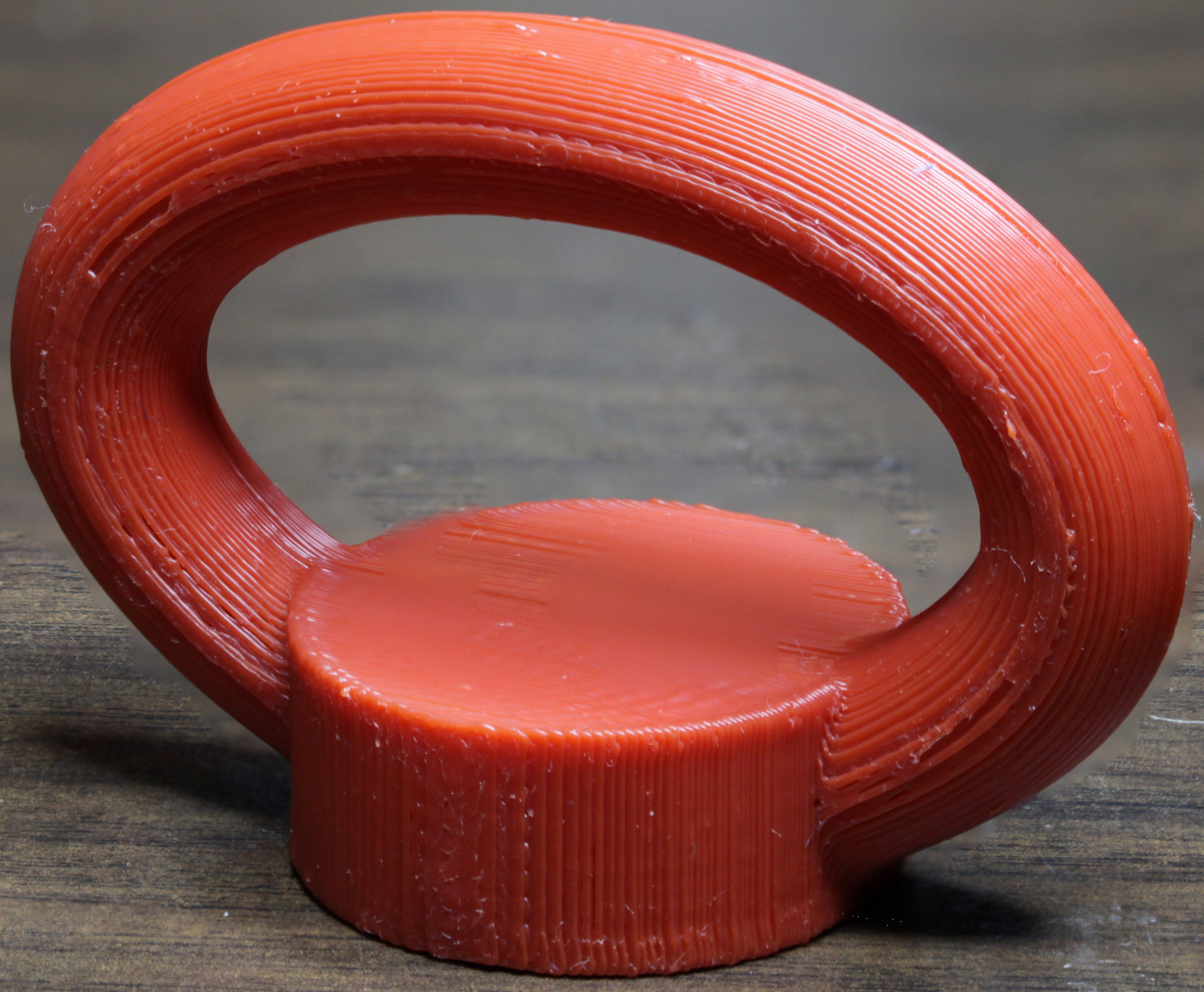
Here's the 3D-printed part:
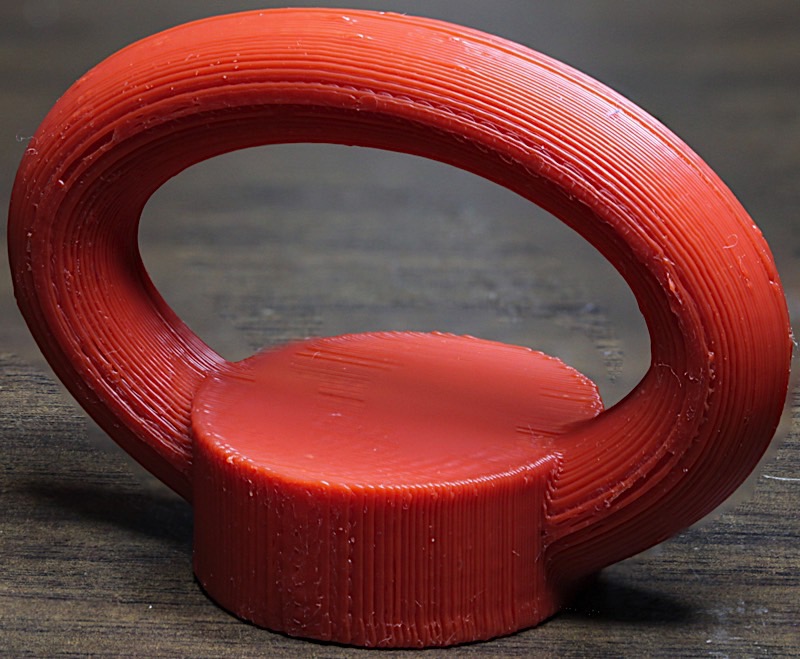
Hi-resolution image shot on Canon EOS 5D MII with focus stacking
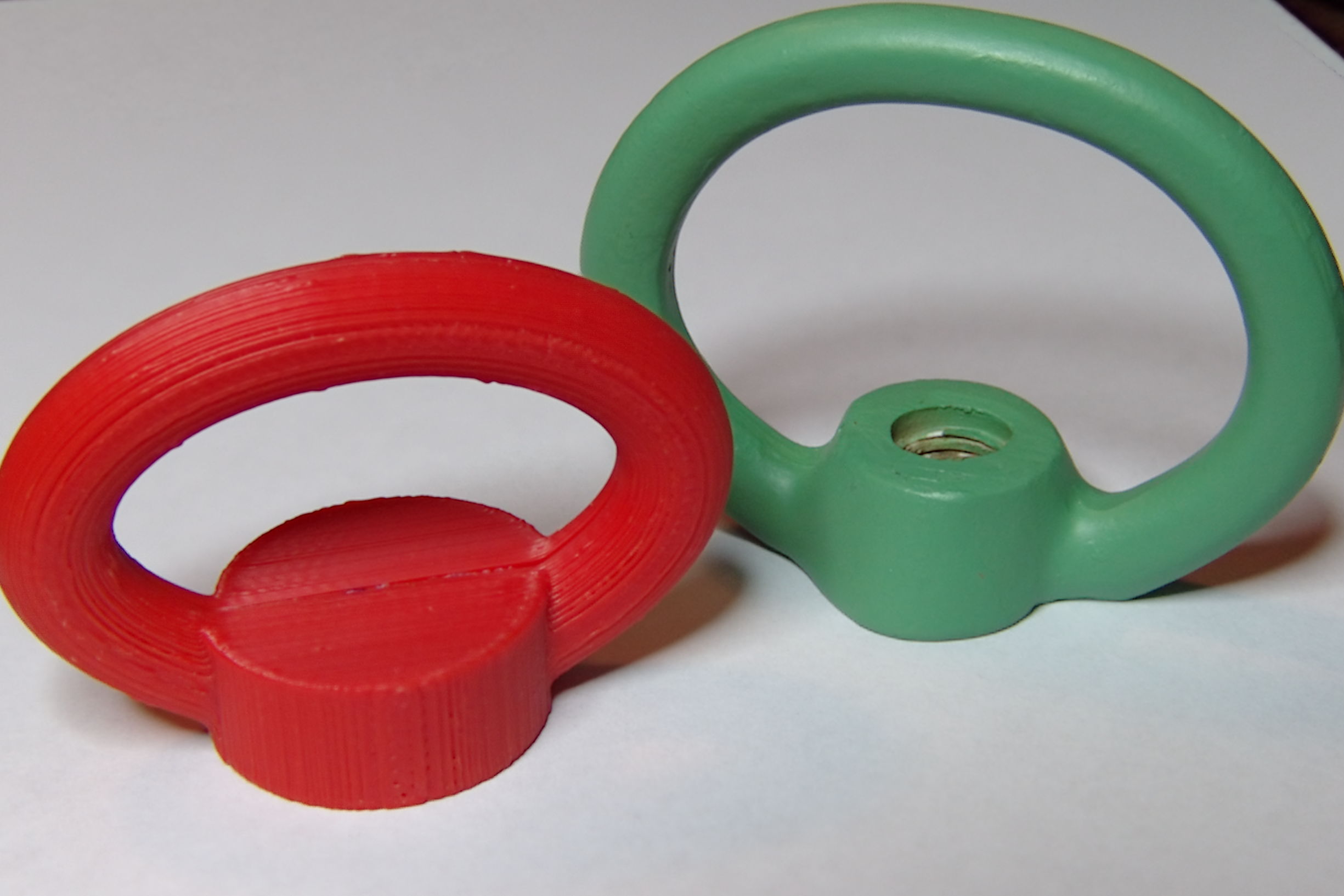
Here they are side-by-side to show their relative sizes. Note that the threaded hole is not present on the 3D printed part; the "latch" is glued onto the port hole rather than bolted.
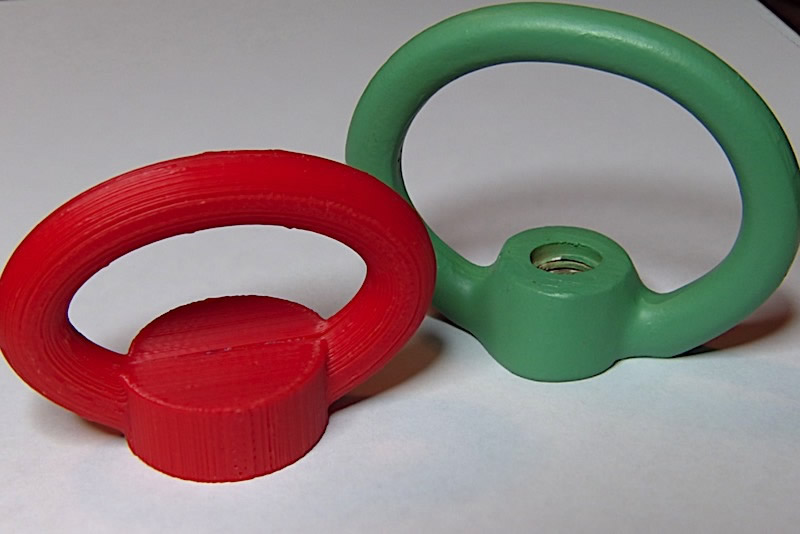
Hi-resolution image shot on Lytro Illum
Final (assembled, painted, and glued to porthole) version:
 Hi-resolution image shot on Canon EOS 5D MII
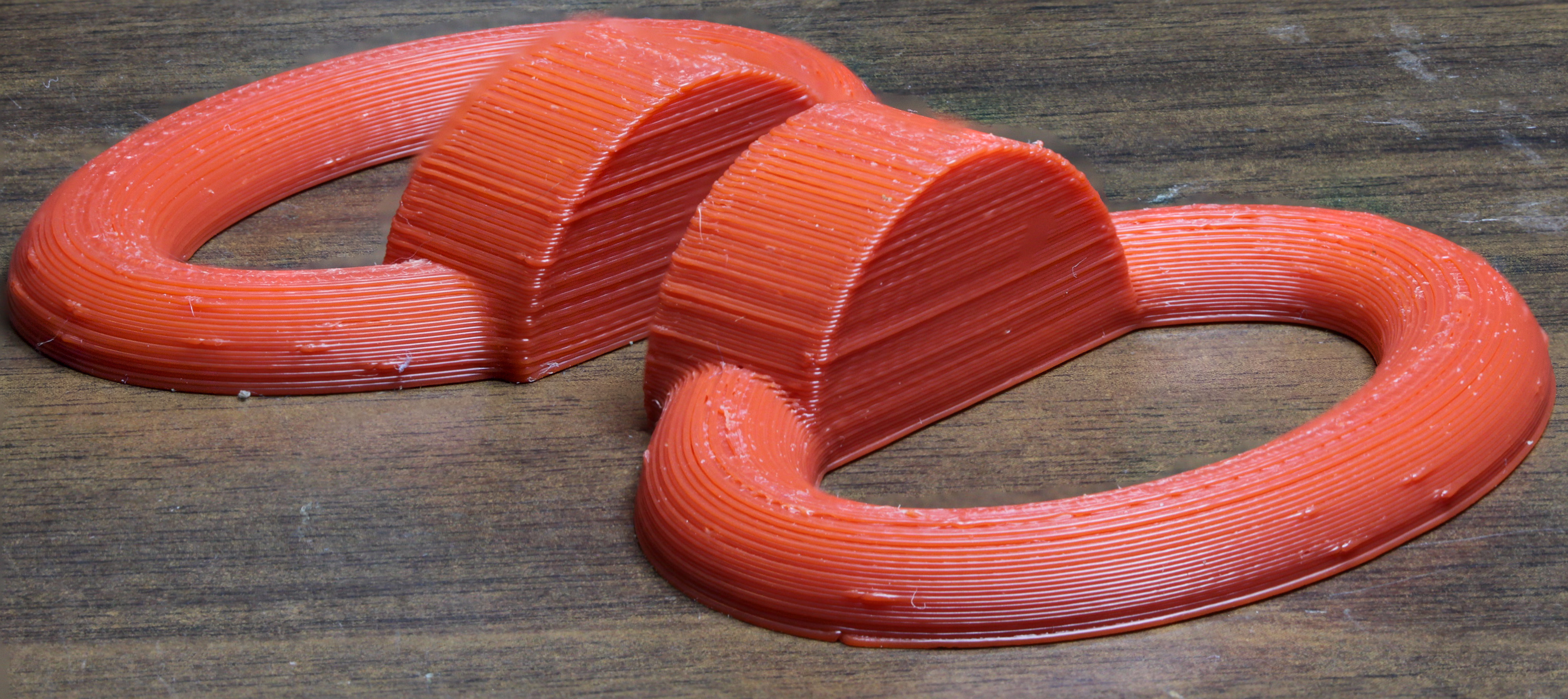
I created this part as two pieces that were glued together after printing:
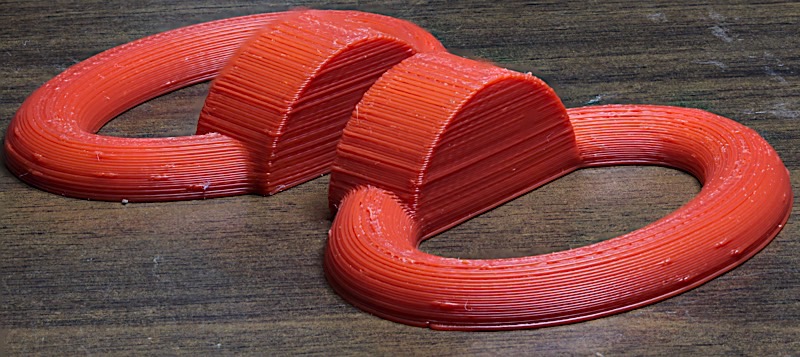
Hi-resolution image shot on Canon EOS 5D MII with focus stacking
There were two reasons for printing this in two pieces rather than as a single piece :
First, by printing it in two pieces I avoided the extra cost and time that would have been needed to print support structures (a significant amount of time when you consider I had to print 56 pieces).
Second, had I printed the part upright (as in the first picture above) the "loop" portion of the object would have been much weaker because the part would have been printed in small horizontal slices going up. By printing the object in two pieces on its side, the loop component was made much stronger. (Granted, as a prop, this device doesn't need a whole lot of strength, but making the piece stronger avoids having to reprint some when a student inevitably breaks one.)
Note that the pictures above are enlarged quite a bit. The base of the latch has a 30mm (about 1.2") diameter.
The Fusion 360 file can be found here: Port Hole Latch v3.f3d.zip
STL files for both halves of the latch can be found here: PortHoleLatch.stl.zip
I was able to fit nine copies of the port hole latch (18 halves) onto a Lulbot Taz 6 build platform.
As the parts were relatively small (and not very high) I got away with using ABS as the print medium.
Here are the relevant Simplify 3D parameters I used to print these parts:
Two processes. Important values listed below.
Process 1
Extruder:
- Nozzle diameter 0.50mm
- Extrusion Multiplier: 1.75
- Extrusion width: 0.75 mm
Layer:
- Primary Height 0.25mm
- Top solid layers 4
- Bottom solid layers 3
- Outline/permeter shells 2
- Outline direction: Outside-In
- First layer height 100%
- First layer width 125%
- First layer speed 7%
Note that the first layer speed is very slow. Doubling the flow rate (Extrusion multiplier) and slowing the 1st layer way down guarantees that the first layer sticks well to the Taz 6 bed. I also put down a layer of Elmer's "Disappearing Purple" glue stick glue prior to the print. Depending on your printer, you could probably run the first layer faster. However, in my experience I'd rather wait an extra half hour to an hour for a slow first layer than to have the entire print mess up later on because one of the parts came loose in the middle of a print.
Additions:
- Skirt layer 1
- Skirt offset 5 mm
- Skirt outlines 1
I always print a one or two-line skirt just so I can verify that the extruder is working and the ABS is sticking to the bed. When printing nine of these, you get an outline around the whole bed, so a single outline is sufficient. I never use a raft because I don't like the texture it leaves on parts. For this particular project, the side stuck to the bed will be glued, so the texture doesn't matter, but why print a raft and waste filament? Of course, if your printer requires a raft, go for it.
Infill:
- Infill percentage 15%
I'd be willing to bet you could get away with 0% for this project (make the part hollow). However, 15% is my standard infill percentage so I left it at that.
Support:
- No support material generation
Infill:
- Primary extruder layer 1 temperature: 240
- Primary extruder layer 2 temperature: 235
- Heated bed temperature: 110
I run the first layer a little hotter so it sticks to the bed better (on the Taz 6, more heat = more stickiness).
Cooling:
- No cooling for ABS
G-Code:
- No changes
Scripts:
- No real changes.
I've made some modifications to my starting script to drop a blob of plastic on the build platform immediately after nozzle alignment. This helps guarantees that ABS is coming out of the nozzle when the skirt starts printing. However, this is completely unnecessary (as one of the reasons for printing the skirt is to get plastic flowing before you start printing actual parts).
Other:
- All default settings.
Advanced:
- Stop printing at height 0.50mm
As the layer height is 0.25mm, Process 1 will stop printing after two layers. Process one is responsible for printing the first layer (at a slow speed and with an increased flow rate). As Simplify 3D does not allow changing the flow rate (extrusion multiplier) on a layer-by-layer basis within a single process, I use two processes in order to control the flow rate. I print two layers (the second layer at the high flow rate and at full speed) because the two processes print in the same direction on their first layers. By printing a second layer in the first process, I get a cross-hatch pattern which is stronger.
Process 2
Extruder:
- Nozzle diameter 0.50mm
- Extrusion Multiplier: 1.00
- Extrusion width: 0.50 mm
Layer:
- First Layer Speed: 50%
- First Layer Width: 100%
Advanced:
- Start printing at 0.50 mm
This causes layer three (first layer in Process 2) to pick up where Process 1, layer 2, left off.
All other parameters are the same as for Process 1. Process 2 basically undoes the high flow rate and width values from Process 1.
Note that the print time for nine pieces on a Luzbot Taz 3D printer with this parameter set is around seven hours. It took six prints to produce the the 54 pieces needed for this project.